Why is the mbed so slow?

20 Mar 2010 . Edited: 20 Mar 2010

Hi again,

I thought I might see what a quick first step might look like. Remember, I'm flying blind so please be gentle! So, the idea is to...

1) change the pins around so at least the bus is on the same port, and redo the wiring - check it all works

2) try a fast version of the write to the port, but nothing else - see if that works

3) Well, if you've got this far, things are looking good - time to continue optimising.

So, here are the details:

1) involves moving to P0.0-P0.11, and for simplicity moving the other pins off port 0, which i think is basically:

// LCD Control
DigitalOut lcd_rst(p21);
DigitalOut lcd_bl(p22);
DigitalOut lcd_rs(p23);
DigitalOut lcd_cs(p24);
DigitalOut lcd_rd(p25);
DigitalOut lcd_wr(p26);

BusInOut lcd_db(p30, p29, p8, p7, p6, p5, p28, p27)

Note, p30 is bit 0, and p27 bit 7. So with that change, and after rewiring all those wires, you should be able to run again and it still work. If not, rinse, repeat.

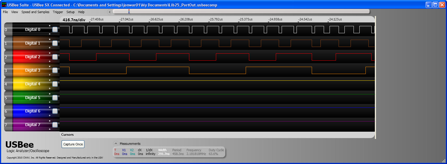
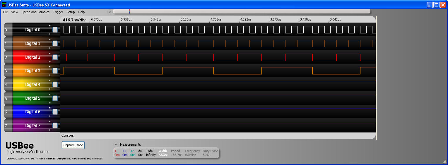
2) involves writing directly to the port. So, something like:

#define BUS_WRITE(v) LPC_GPIO0->FIOPIN = v << 4

void TSLCDOutDat(unsigned short dat) //write data to LCD
{
    lcd_rs.write(1);
    lcd_rd.write(1);
    lcd_wr.write(0);
    lcd_db.output();
    BUS_WRITE(dat >> 8);  // substitue direct write line
    lcd_cs.write(0);
    lcd_cs.write(1);
    BUS_WRITE(dat);  // substitue direct write line   
    lcd_cs.write(0);
    lcd_cs.write(1);
    lcd_wr.write(1);
    lcd_db.input();
}

void TSLCDOutDat2(unsigned char dath,unsigned char datl) //write data to LCD
{
    lcd_rs.write(1);
    lcd_rd.write(1);
    lcd_wr.write(0);
    lcd_db.output();
    BUS_WRITE(dath);  // substitue direct write line   
    lcd_cs.write(0);
    lcd_cs.write(1);
    BUS_WRITE(datl);  // substitue direct write line   
    lcd_cs.write(0);
    lcd_cs.write(1);
    lcd_wr.write(1);
    lcd_db.input();
}

And then see if that works.

Note, it only changes two of the functions, and is just a raw write to the port with no mask, so not quite how you'd actually do it and and doesn't do anything for the other pins or input/output, but i'd hope it'd be enough to measure a difference to show it working. The idea being if it doesn't work, not much has changed so the bug should be easier to track down. And if/when it does, then it is time to do it properly, and for the other pins etc. i.e. 3)

Simon

20 Mar 2010 . Edited: 20 Mar 2010

Had a chance to ponder the Port API request a little. Trying to define the semantics, my first attempt is:

  • Allow you to be able to write to a whole port in a generic way
  • Provide a mask for the port so only some pins in that port are updated
  • Play nicely with anything else that might share that port (i.e. don't stop any other DigitalOut etc stop working)

The third I think is important; if i use 5 bits as a port, I don't want to effectively have to hijack the whole port/stop anything else working.

Given these requirements, the two obvious approaches for implementing it on the LPC I/O architecture is to:

  • Set the MASK and write to PIN
  • Create a set and clear pattern and write to SET and CLR

Whilst using MASK is the natural stand-alone approach, you would theoretically have to clear the mask after every transaction otherwise any other things interacting with that port will be impacted. Therefore, I thought i'd actually go with the SET/CLR approach for now.

Here is a first go:

#include "mbed.h"

enum PortName {
    Port0 = LPC_GPIO0_BASE,
    Port1 = LPC_GPIO1_BASE,
    Port2 = LPC_GPIO2_BASE,
    Port3 = LPC_GPIO3_BASE,
    Port4 = LPC_GPIO4_BASE
};

class PortOut {
public:
    PortOut(PortName port, int mask = 0xFFFFFFFF) {
        _mask = mask;
        _port = (LPC_GPIO_TypeDef*)port;
        _port->FIODIR |= _mask;
    }
    
    void write(int value) {
        uint32_t s = value & _mask;
        uint32_t c = (~value) & _mask; 
        _port->FIOSET = s;
        _port->FIOCLR = c;
    }

    LPC_GPIO_TypeDef *_port;
    uint32_t _mask;    
};

PortOut x(Port1, 1 << 20 | 1 << 21);

int main() {
    while(1) {
        x.write(0xFFFFFFFF);
        wait(0.2);
        x.write(0);
        wait(0.2);
    }
}

So, you construct a PortOut and provide the port number, and the mask of the bits you want to write on that port. Then, when you write, only those bits are updated. In this example, I'm writing all 1s then all 0s to the port. Because of the mask, only P1_20 and P1_21 (LED2, LED3) will get updated.

This approach allows you to create multiple PortOut's, even with ports based different bits on the same port which is pretty flexible I think. The approach is never going to be as fast as if you hard code everything knowing everything about your application and the other users of the I/O, but it'll be pretty close.

I'd be really interested in ideas and feedback on this one.

Simon

30 Aug 2010

Hi to all

I have same trouble ... I tried previous Simon's post and issue is still same

I try to understand this last post with mask and write ... but I did not sucess :(

this demo picture is displayed for about 10 seconds :(


30 Aug 2010

Hi Tomislav,

PortOut is now officially supported, see:

So using this should make it go much faster! Please report back with how you get on.

Simon

31 Aug 2010

I was just wondering if anybody had a chance to test out the new portOut.  I've been testing the following code ande I was wondering if anybody could explain the behavior I am seeing.

Code:

// Counter

#include "mbed.h"

//Port 2 : 0,1,2,3
//P_26,P_25,P_24,P_23;

#define counter_MASK 0x0000000f

PortOut counter(Port2, counter_MASK);

int main() {
    while(1) {
        counter = 0x00000000;
        counter = 0x00000001;
        counter = 0x00000002;
        counter = 0x00000003;
        counter = 0x00000004;
        counter = 0x00000005;
        counter = 0x00000006;
        counter = 0x00000007;
        counter = 0x00000008;
        counter = 0x00000009;
        counter = 0x0000000A;
        counter = 0x0000000B;
        counter = 0x0000000C;
        counter = 0x0000000D;
        counter = 0x0000000E;
        counter = 0x0000000F;
    }
}

Result from logic analyzer:

Signals are in the following order:
P_26
P_25
P_24
P_23

Maybe I am missing something, but I do have everything hooked up correctly.  Also, is there a way to fix the execution time of a port write command?  If I run the following:

Portout = 0x00000001;
Portout = 0x00000000;
Portout = 0x00000001;
Portout = 0x00000000;

I don't get a 50/50 duty cycle.

Also, in case anybody is wondering, the frequency of the topmost signal in the image above (P_26) is ~5MHz.

Thanks!

Tyler

31 Aug 2010 . Edited: 31 Aug 2010

That's strange. If it's not software related, it could be that the pulses are too narrow and you're actually getting and exponential rising and falling edges and the triggering could be skewed. Check it under a scope if possible.

Edit: I just checked with my scope and your results are sound. The frequency is 4.786MHz and the duty cycle is 74.6 % of the LSB.

31 Aug 2010 . Edited: 31 Aug 2010

Thanks for checking that!  I was beginning to think something was wrong with my setup.

I was thinking about this a little more... I'm going to make an assumption that PortOut is constructed similarly to the example Simon posted earlier?  (A write first performs a set then a clear).  I can believe that looking at the waveform above... rising edges happen before falling edges.

One question I have is, why does it take so long between the rising transition and the falling transition... For instance, when count goes from one to two, there is ~50-60ns between the set command and the clear command.  Isn't that like 5-6 clock cycles?

Thanks!
Tyler

31 Aug 2010 . Edited: 31 Aug 2010

Hi Tyler,

Yep, they are implemented as a set/clear pair, hence the results. When I did the benchmarking, this came out on top, but in hindsight i'm not sure this is the best choice as it gives slightly unexpected results.

I think the answer may actually be to implement this as a read-modify-write; slightly more bit-munging necessary, but it is reading/writing peripheral registers that is slow, so it'll still only be two accesses. It'd also give the more expected behaviour of the transitions happening at once.

I'll get some tests done and see how the results come out.

Simon

31 Aug 2010

Hi Simon thanks a lot for this hint ... I dont have updated mbed library in compiler :) ...

I am newbie into 32bit controllers and mbed too :) so I must handle some beginner problems :)

but I have some questions regarding PortOut / PortIn usage

is it possible to define PortIn and PortOut in this way ?

#define LCD_MASK 0x00000ff0
PortOut lcdPortOut(Port0, LCD_MASK);
PortIn  lcdPortIn(Port0, LCD_MASK);
and later in code to use

void TSLCDOutDat(unsigned short dat) //write data to LCD
{
    lcd_rs.write(1);
    lcd_rd.write(1);
    lcd_wr.write(0);
        
    lcdPortOut = dat >> 8;

    lcd_cs.write(0);
    lcd_cs.write(1);

    lcdPortOut = dat;

    lcd_cs.write(0);
    lcd_cs.write(1);
    lcd_wr.write(1);
}
for sending  data to display

unsigned short TSLCDInDat(void) //read data from LCD
{
    unsigned short dat = 0;

    lcd_rs.write(1);

    lcd_wr.write(1);
    lcd_rd.write(0);

    lcd_cs.write(0);
    lcd_cs.write(0);
    dat = lcdPortIn.read();
    lcd_cs.write(1);

    dat <<= 8;

    lcd_cs.write(0);
    lcd_cs.write(0);
    dat |= lcdPortIn.read();
    lcd_cs.write(1);

    lcd_rd.write(1);

    return (dat);
}
to read data from LCD ...


thanks in advance :)


03 Sep 2010

A new version of the library has been released, which makes the duty cycle a lot better (plus makes it slightly faster):

Before:

Version 25 PortOut

After:

03 Sep 2010

Thanks! That's awesome.

03 Sep 2010

Hello everybody ..again :)

I try to update mbed library to v.26 and I cant see any big improvements ( in my/our aplication ) ... I dont blame ...

display is still so slow  but finaly i get familiar with PortInOut library and speed is rapidly increased ...

some videos are attached ... sorry for may handshaking :-/

with BusInOut ...v.26

with PortInOut used

there are some glitches i think that I have some bad code in command send routine or display settings


-deleted-
14 Mar 2011

Hi guys,

How did someone get 48MHz I/O speed, I have only ever been able to reach 24MHz and that was with direct registry access.

using: LPC_GPIO0->FIOCLR = 0x07800000; LPC_GPIO0->FIOSET = 0x07800000;

In addition is there any further developments/benchmarking been done on mbed I/O speed. I haven't done much with the mbed recently as I just felt it could achieve the speeds I wanted.

I have started to look at the mbed again in the hope it has grown an would be able to acheive what I want.

If i can get the speed required (<40nS if possible) the I would probably use the lpc1768 on a pcb.

I want to be able to have an external SRAM interface to a 4Mbit SRAM with a 16bit data bus.

I would also want a data bus connecting another controller possible a second lpc1768.

The idea being that I have an LPC1768 reading inputs from a controller.

This LPC1768 reads the input and outputs a 8/16/32bit command to the second LPC1768.

The second LPC1768 reads the instruction from the first LPC1768 and performs data manipulation on image data stored in external SRAM according to the code is recieves from the first LPC1768.

So within the second LPC1768 it may have a lookup table that says if i recieve instruction 0x00780000 then move image starting at 100,100 with a width of 100 and height of 100 to have a starting point of 300,300.

This means that the second lpc1768 reads and writes data from the SRAM to alter the position of the image as the specified location.

Then using a bus exchanger the SRAM is then flipped to the FPGA which is acting as a VGA controller in this system.

The display resolution I am going to use is 640 x 360 which is 16:9 aspect ratio. This is because 640 x 360 fits into 4Mbit SRAM when 640 x 480 at 16bpp doesn't.

The pixel clock of 640 x 480 at 60Hz is 25.175MHz hence the want for an I/O speed of <40nS so I could completley change the frame of an image at 60 frames/sec.

I understand I wont reach that level due to the calculations/lookups the second LPC1768 will need to do, however I would like to get as close as possible.

I would be will to settle for a level of 30 frames/sec, but need to aim high first to give myself room to come down.

I would be designing a PCB that would contain 2 LPC1768's and 1 small FPGA probably from Xilinx in QFP form.

I want to use 2 LPC1768's because I think manipulating the data in external SRAM will be enough work for it to do and I think that if i tried to get it to read controller buttons an calculate where things moved on a screen I would loose too much performance in the way of frame rates, given I believe it will struggle as it is.

The point is to make a basic games console, probably on the level of the SNES (Hopefully Better)

So....After that long essay of trying to explain what I am trying to achieve.

I would like to know if what I want to achieve with the I/O is possible or should I just look at another device and if so some suggestions of microcontrollers with fast I/O would be very helpful.

On a final note, I would like to avoid BGA's and QFN's as I intend to solder this myself, and although I have the means to get a bga down, I would rather not have to as it becomes very expensive if it goes wrong.

Thanks in advance guys, hope someone can help

Edit: Brief decription of how one operation might work.

player presses right on controller pad.

mbed1 reads controller pad inputs

mbed1 detects right button pressed

mbed1 knows a right button press means move sprite 10 pixels right

mbed1 determines current sprite location is 100,100

mbed1 knows sprite is 100,100 big

mbed1 sends code to mbed2 (0x00780000)

this means move image starting at location 100,100

to location 110,100

with a width/height of 100,100

fill location left empty by move with background texture

fill 100,100 to 109,200 with background texture

mbed2 recieves code

mbed2 looks up what code means

mbed2 carrys out sram read and writes to move image

mbed2 controls the buffer enchanged device to flip the SRAM memory so it will be used by the FPGA

fpga continuously reads from the sram ram it is using and using logic within it outputs a VGA video signal