AnalogIn problem

05 Jan 2010 . Edited: 05 Jan 2010


Rob Dobson wrote:

I have now added some stats calculations to the ADC capture test and published here: http://mbed.org/users/Bobty/programs/gpdz5c

My results for low noise situations (I have taken used short cables and a 1nF capacitor between p20 and ground - although the MBED is still on a breadboard and connections are made through the breadboard) with the CLKDIV values of 25 and 200 are:

CLKDIV = 25

Mean: 184.19                Std-dev (highest, lowest): 10.27, 0.68
Deviation Table
Dist.   Count
0       87184
1       13367
2       1252
<snip>
> 10    2

CLKDIV = 200

Mean: 183.92        Std-dev (highest, lowest): 0.71, 0.62
Deviation Table
Dist.   Count
0       88949
1       11185
2       1791
<snip>
> 10    0

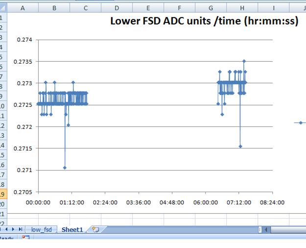
Looking at the stats and thinking about this, there isn't much difference at the low deviations for different clock speeds, the main difference is at the high deviations. What I suspect is that the lower clock simply means that the ADC is missing more of the glitches that are occuring at  the analog inputs, rather than it is converting better. If this is the case, then it's probably better to use the higher rate and do an average with discard of outliers. This might best be implemented as an interrupt driven process happening in the background.


Dave

05 Jan 2010 . Edited: 05 Jan 2010

I am not familiar with the implementation of the analog input on the ADC pin.  However, I do know that if an analog signal is sampled digitally by any converter, it MUST be filtered such that the bandwidth of the analog signal input to the digital converter is at MOST half of the sample rate.  This is to prevent aliasing of the signal into the converter.  If the analog input signal to and ADC is not filtered in any way, then it is very reasonable to see "spurious" values, as these could be occuring at any frequency above the sample frequency, and being aliased by the ADC during its sample period.  No amount of software processing will remove these spurious values, as they must be filtered out prior to digital sampling.  Perhaps this is the source of frustration that Rob is experiencing, because if an input signal to the ADC contains out of band noise, it will show up on the ADC as 'spurious' values, and cannot be removed in software.

The only way to prevent this source of input degradation is to filter the incoming analog signal to be within a bandwidth of less than half of the sampling frequency of the ADC.  Calling it noise is somewhat misleading, as the problem here is not so much with noise, which tends to be random, but with out of band noise, which can oftentimes appear as spurious.  It is this out of band noise that requires the filtering.  Also, you could easily test this, if there is no filtering, and see this if you were to apply a signal at , for example, 30 Hz, while sampling at 50 Hz, and the system would read it in and tell you that there was a signal at 20 Hz.  This is due to aliasing of the out of band signal (30 Hz), wrapping back into the bandwidth (25 Hz), set by the sample rate of the ADC (50 Hz).

I just got my boards yesterday, so I have not played around with much of any of this yet, but I wanted to chime in, because I thought maybe this information might be helpful, because it seems like there is an attempt to apply a digital solution (software) to an analog problem.  Analog design can be tricky, as some have pointed out, referring to separate isolated analog power supplies and extra ground planes, etc., but a 10-bit A/D is low resolution, and shouldn't require a significant amount of analog design effort.  However, the input to an ADC should ALWAYS be buffered and filtered to the correct bandwidth be at most half the ADC sample rate.  Also, another note, if you just hook up wire leads to a high input impedance directly with no filtering, you have an antenna.

08 Jan 2010

Thanks to the "snow day" off, I've had a chance to experiment with a view to producing two clean analog inputs to read a Nintendo DS touchpad. Long story short - several experiments. The only decent result came from a ground plane from Dave and capacitors from that to the analog input pins (17 and 20). 10nF caps did the trick - almost noiseless with 1 - 3 x lsb excursions occasionally. Tried it at full speed and with delays between the reads but no difference. I think the "micro code" is OK.  Scaled and offset the touchscreen inputs to correlate to the Nokia lcd pixels and got a scribble pad - very satisfying. Next stage - a full touch keyboard and mini graphics pad.

Pip

09 Mar 2010 . Edited: 09 Mar 2010

Hi,

I am having spike issues with the ADC. I have written a test program that samples all six channels at maximum rate and prints the min, average and max as a bar every second.

ADC_spike

I have tried soldering the ground plane as described earlier in the thread but I'm still seeing full scale spikes everywhere.

I am feeding all six ADC pins with DC with a 47uF/100nF on each ADC pin to ground and through a 10k resistor for each pin. Quite well filtered.


Update: I re-checked just for one channel and it seems to work with no spikes now. I'm confused but relieved that I am at last getting sensible readings. I think there were some bugs in the code I just published. Here is a new working version that only tests pin 20 at maximum sample rate.

ADC_spike

18 Sep 2010

Adding to this discussion.  I recorded Voltages sampled at maximum rate. The input channel was 0 (p20) filtered by a low pass filter with break point frequency of 159Hz.  Each data point is an average of 10 readings.  The shift in voltage 6 1/2 hours later ( for lower FSD and
~ 8 hours Near FSD )was due to the drift in the source  ( power supply).  The mbed unit (LPC1768) mounted on strip board connected to a wireless router 1m distant.  Data was collected by a web server running on the mbed  - see my programme - server31


Below is the record  with the input voltage near FSD. Noise is less at FSD  with outliers at +/- 1 E-3  ~ 3mV


Regards


Paul

18 Feb 2011

Simon/Anyone,

What is the update rate for any given ADC channel using the library routines. I am assuming the channels are being updated in the background with the latest values being available in the call or is this incorrect? I hope it does not just hang on a read call!

Greg

19 Feb 2011

@Greg:

I have measured the AnalogIn time as 72 microseconds per conversion. Your code blocks while the conversion occurs.

You can change the clock speed of the ADC after a call to the AnalogIn constructor and set it to 12MHz; that gets the conversion time down to about 8 or 9 microseconds.

It is also possible to write code (it's available in one of the libraries) to put the ADC into BURST mode and have conversions occur in the background.

Please look at the thread AnalogInAnalyzer (and others) to see some of the problems one can run into using the onboard ADC: it is very sensitive to noise on its inputs and "glitches".

Bob

21 Feb 2011

Thanks Bob.

My application is in some multicopter flight control code and the analog inputs are one of the bottlenecks. My own code on another platform did the normal overlapped read and then trigger the next conversion. I will chase down the BURST mode code.

The glitching is an issue. I have some digital low pass filtering in so that may moderate it. The cost of putting in some explicit windowing is not that difficult as well probably. Fortunately the analog inputs are not directly related to flight control being battery monitoring etc. but one version of the code can use analog IR sensors in which case I need to take some care.

Another issue is the tendency for the I2C buss to hang - most of my sensors are I2C and having the flight control go bye byes for an indeterminate period of time is not really acceptable.

Cheers Greg

28 Feb 2011

http://ww1.microchip.com/downloads/en/AppNotes/00688b.pdf

here is an appnote describing layout tips with ad converters.

Torfinn Sornes

28 Feb 2011

Here is another from NXP:

http://www.nxp.com/documents/application_note/AN11031.pdf

Also, some of the Analog Devices and Burr Brown (now part of TI) application notes concerning ADC layout and noise issues are quite good. Since these two companies have been producing precision analog and high resolution ADC/DAC products for decades they have a great deal of analog application knowledge.

http://focus.ti.com/analog/docs/analogtechdoc_hh.tsp?viewType=mostuseful&rootFamilyId=82&familyId=82&docCategoryId=1

http://www.analog.com

Hope this is helpful.

Doug

02 Mar 2011

/media/uploads/Rigaud/rapport_test_adc_mbed_f_r_01-03-2011.pdf

This is a numerical filter to MBED ADC, it is not my job, maybe it could be better, Best regards, François Rigaud /media/uploads/Rigaud/main_test_filter_adc_francois_rigaud.cpp

12 Mar 2011

Hi Simon,

The ADC_Spike program and other ADC code you wrote all contain a typo in adc.h.

#define CLKS_PER_SAMPLE 64

should read:

#define CLKS_PER_SAMPLE 65

As it takes 65 PCLK cycles for a single conversion according to the LCP datasheet.

Could you please correct this and publish ADC.h and ADC.cpp as a library?

29 Mar 2011

Hi All,

almost pulled out my remaining hair in wrestling with the glitch problem. Finally got it solved, though. Mainly because of your input to this thread, so thanks to you all!

It seems to be, indeed, caused by noise. But not random noise or noise in the signal. Instead, the mbed somehow generates recurring spikes (possible candidate: USB housekeeping messages, spikes are regular enough to allow time based locking on to the glitches! Didn't have time to test this hypothesis with a battery and a serial link. 9V battery alone in Vin effectively disconnecting the USB power input didn't help), which trigger an interesting instability in the ADC. Were this ordinary noise, the error would have some kind of sensible distribution, which it hasn't. As already noticed on this thread, the glitch values are very often either 0x000 or 0xfff. My guess is that the ADC itself through its switching during the successive approximation injects noise into the signal and the high high frequency impedance in the input causes the approximation to run havoc.

The PCB design of mbed is a bit 'challenged' to say the least. The single gnd positioned in the corner is a troubling sign. Dave added the ground plane to his mbed which hinted me to try filtering the ADC input (p15 in my case). The glitches showed extreme correlation to the length of the capacitor leads - much more so than to the capacitor value. When the leads were minimal i.e. just enough to reach the p15 from the ground pin, the glitches vanished completely! In this case the ceramic capacitor value was 10 nF. Most likely there would be a better connection point on the mbed PCB itself, but since this worked for me and I have to catch up the lost time, I leave it to someone more interested.

Once again, thanks to you all! Now it works.

05 Jun 2011

Karri Palovuori wrote:

Hi All,

almost pulled out my remaining hair in wrestling with the glitch problem. Finally got it solved, though. Mainly because of your input to this thread, so thanks to you all!

It seems to be, indeed, caused by noise. But not random noise or noise in the signal. Instead, the mbed somehow generates recurring spikes (possible candidate: USB housekeeping messages, spikes are regular enough to allow time based locking on to the glitches! Didn't have time to test this hypothesis with a battery and a serial link. 9V battery alone in Vin effectively disconnecting the USB power input didn't help), which trigger an interesting instability in the ADC. Were this ordinary noise, the error would have some kind of sensible distribution, which it hasn't. As already noticed on this thread, the glitch values are very often either 0x000 or 0xfff. My guess is that the ADC itself through its switching during the successive approximation injects noise into the signal and the high high frequency impedance in the input causes the approximation to run havoc.

The PCB design of mbed is a bit 'challenged' to say the least. The single gnd positioned in the corner is a troubling sign. Dave added the ground plane to his mbed which hinted me to try filtering the ADC input (p15 in my case). The glitches showed extreme correlation to the length of the capacitor leads - much more so than to the capacitor value. When the leads were minimal i.e. just enough to reach the p15 from the ground pin, the glitches vanished completely! In this case the ceramic capacitor value was 10 nF. Most likely there would be a better connection point on the mbed PCB itself, but since this worked for me and I have to catch up the lost time, I leave it to someone more interested.

Once again, thanks to you all! Now it works.

Just want to say that using the experimental firmware and semihost_powerdown() reduced the noise on the ADC lines for me... on all except pin19... not sure why that pin remains noisy...

Now to figure out how to increase the ADC clock, I need faster conversions ;)

06 Jun 2011

Just want to tell i have the same problem on mbed (LPC1768), lpcxpresso (LPC1769) (both put on grid-style PC board (small circles with copper on PCB)).

I have a KEIL MCB1700 with a LPC1768 on it, potentiometer on Analog in and there the same code is working. No false reading, at least as far as i have seen.

Quote:

Just want to say that using the experimental firmware and semihost_powerdown() reduced the noise on the ADC lines for me... on all except pin19... not sure why that pin remains noisy...

Now to figure out how to increase the ADC clock, I need faster conversions ;)

Can you tell me where to get the experimental firmware for mbed ? Is known what was changed ? What is semihost_powerdown doing ? Something with debugging / SWD / SWO ? When you say, you see no more problems, have you changed something around mbed (like used capacitors, ground planes, ...) ?

06 Jun 2011

@Martin

The experimental firmware allows one to switch off the USB interface chip on the underside of the Mbed board, using a function called semihost_powerdown(). I initally did this to save power as I didn't need the USB interface, but I found that switching it off removed all the random jitter I was getting on my ADC pins. I always perform a small degree of averaging (usually 5 samples), but on this test design I am plugged into an ordinary proto typing board with no caps to ground (which would have been my evental solution to filter out noise, probably will still add some anyway if I develop this further)...

06 Jun 2011

Also want to note that setting the ADC clock to 25Mhz also seems to help reduce jitter... perhaps the slow capture time makes the ADC hardware more susceptible to electrical activity from the "interface chip"?

Code: software-controlled ADC settings LPC_ADC->ADCR = (0 << 0) SEL: 0 = no channels selected

(1 << 8) CLKDIV: PCLK max = 25MHz, /25 to give safe 1MHz, (1 = 8us ADC time)
(0 << 16) BURST: 0 = software control
(0 << 17) CLKS: not applicable
(1 << 21) PDN: 1 = operational
(0 << 24) START: 0 = no start
(0 << 27); EDGE: not applicable
06 Jun 2011

Are you guys talking about v29 beta? If so, then analogIn.read() has a median filter to filter spikes.

See http://mbed.org/forum/bugs-suggestions/topic/1980/?page=1#comment-9929

06 Jun 2011

Igor Martinovski wrote:

Are you guys talking about v29 beta? If so, then analogIn.read() has a median filter to filter spikes.

See http://mbed.org/forum/bugs-suggestions/topic/1980/?page=1#comment-9929

No, I'm using V28... The median filter seems nice, but I will need to test it... I don't want to lose the 8us conversions I'm currently getting :)

07 Jun 2011

I agree. It's more of a stop-gap solution than an actual fix of the problem

07 Jun 2011

I have used 50 105mhz ferrite beads that have helped me and ferrite bead usb cable, at the moment no errors no clicks, it has been supressed anyway.

07 Jun 2011

@all Can you tell me with which processors it happens on your side ? Is it happening e.g. only with LPC17xx series or also with LPC23xx ?

07 Jun 2011

for me it is the LPC17xx, but no doubt everybody sitution is different, my sitution I believe was coming from my vacuum tube microphone which is powered by the mains supply, Not sure if it was noise generated by it or if it was acting as a antenna. But the dirty power supply and micophone acting as antenna seem to be the problem and then perharps the usb cable?.

07 Jun 2011

I thought I would add this as well I have certainly noticed the difference a breadboard can make

Bob Pease's breadboards aren't the type of breadboards we discuss here (solderless breadboards). He is known to use coper-clad boards for breadboarding.

http://www.national.com/rap/Story/0,1562,8,00.html

07 Jun 2011

I think the V29 AnalogIn will probably fix this issue for most people.

On a related note, I think I now understand the ADC hardware enough to write a new AnalogIn class, I hope to write a library that will allow user setting of the ADC clock and also set the burst mode, set the amount of filtering (so the user can tune performance) and attach a callback function etc... I will follow the Mbed API closely so it should be a drop in replacement in existing code. Watch this space I guess :)

07 Jun 2011

Matt Parsons wrote:

I think the V29 AnalogIn will probably fix this issue for most people.

On a related note, I think I now understand the ADC hardware enough to write a new AnalogIn class, I hope to write a library that will allow user setting of the ADC clock and also set the burst mode, set the amount of filtering (so the user can tune performance) and attach a callback function etc... I will follow the Mbed API closely so it should be a drop in replacement in existing code. Watch this space I guess :)

What makes V29 different?

07 Jun 2011

Philips Philips wrote:

Matt Parsons wrote:

I think the V29 AnalogIn will probably fix this issue for most people.

On a related note, I think I now understand the ADC hardware enough to write a new AnalogIn class, I hope to write a library that will allow user setting of the ADC clock and also set the burst mode, set the amount of filtering (so the user can tune performance) and attach a callback function etc... I will follow the Mbed API closely so it should be a drop in replacement in existing code. Watch this space I guess :)

What makes V29 different?

The V29 mbed library has a median filter in the capture code, this will select the middle value of the three samples taken (or some such similar algorithm)... this will smooth out the jitter, at the cost of performance (though this should not be a problem, as acquisitions are faster in this library).

07 Jun 2011

Matt Parsons wrote:

Philips Philips wrote:

Matt Parsons wrote:

I think the V29 AnalogIn will probably fix this issue for most people.

On a related note, I think I now understand the ADC hardware enough to write a new AnalogIn class, I hope to write a library that will allow user setting of the ADC clock and also set the burst mode, set the amount of filtering (so the user can tune performance) and attach a callback function etc... I will follow the Mbed API closely so it should be a drop in replacement in existing code. Watch this space I guess :)

What makes V29 different?

The V29 mbed library has a median filter in the capture code, this will select the middle value of the three samples taken (or some such similar algorithm)... this will smooth out the jitter, at the cost of performance (though this should not be a problem, as acquisitions are faster in this library).

Ok cool my problem got fixed with ferrite beads tho, don't like the sound of performace loss, maybe you could explain more on what would be lost:)

07 Jun 2011

Philips Philips wrote:

median filter

Oo I just read http://en.wikipedia.org/wiki/Median_filter I don't like that:) I like lossy speech codecs tho:)

08 Jun 2011

Hi

IMHO Software filtering is not a soltution but supressing problems in either input (sometimes you just cannot change this because noise exists) or hardware (thats most of the time due to design faults).

Personally I would never filter the adc input during aquisition nor stored fitered input (so always store raw data) but do the filtering on a PC (In a previous project we did the spike filtering on the pc). Just store the filtering parameters on the pc and re-apply them during each visualisation of your data.

That way you can still adjust/remove filtering for further analysis.

Wim