Michele -
What about attacking from a totally different direction?
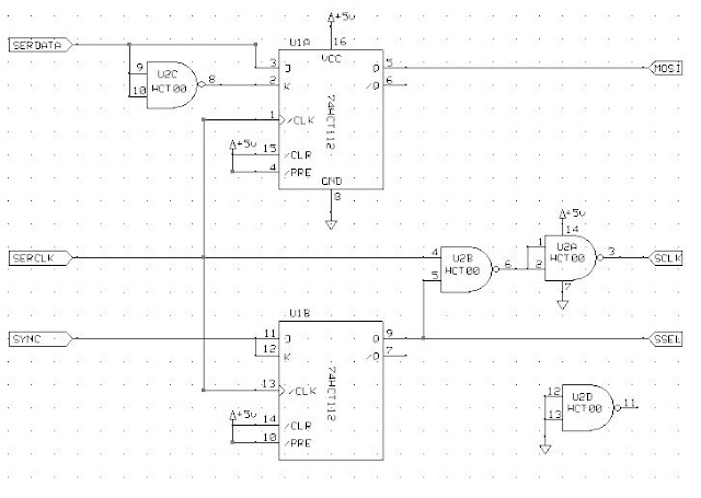
Here is a back-of-the-envelope design for a simple two-chip test circuit that eliminates the back-to-back transfers. The idea is to discard every other sample from the GPS.
It uses one 74HCT112 negative-edge triggered J-K flip/flop, and one 74HCT00 quadruple NAND gate.
Referring to the schematic diagram below, here is a description of the operation.


Flip/flop U1B divides the SYNC signal by 2 before passing it on to the SSEL pin of the mbed. Thus, the mbed's SPI module will be selected for the interval between one SYNC pulse and the next, so it will capture the 16 bits of data that intervene. Then SSEL drops for the interval between the second SYNC pulse and the third, which effectively discards the next 16 bits of data. The cycle repeats continually. The flip/flop changes on the negative edge of SERCLK, so it captures the change in SYNC that happened on the preceding rising edge.
The SSEL signal is used to gate the SERCLK (via U2B) before passing it on to the SCLK pin of the mbed. This produces bursts of 16 clock cycles, synchronized to SSEL.
Finally, flip/flop U1A is used to delay SERDATA by one-half SERCLK cycle, before passing it along to the mbed's MOSI pin. This delay is needed to maintain the timing relationship between clock and data.
One important note -- with these changes, the active edge of the SPI clock becomes the **rising** edge. The mbed needs to be configured correspondingly, which I assume is possible (if not, try removing U2A which will un-invert SCLK).
Here is what the timing should look like (please ignore the labels to the left of the traces - they are artifacts


Hello mbed community,
I have to read a GPS front-end output with my mbed. This is serial stream of bits running at 6.5MHz (see below)
Basically it can be considered as a 1-bit ADC with two outputs (clock and data): the clock runs at 6.5MHz and the data is 1bit wide. I have been reading a bit about mbed and so far my candidates buses are SPI (SSP) and I2S. I have some doubts about both though.. namely the SPI likes framing and the I2S is usually used at much lower speeds.
I just tried the SPISlave library so far,
connecting p11 (MOSI) to the data line, p13 (SCK) to the clock, and shorting a mbed DigitalOut pin with the "chip select" of the SPISlave on p14:
but this code
    //
    // GET THE DATA SNAPSHOT FROM THE GPS FRONT-END
    //
    // Disable the reception of data from ADC for the moment
    mbedCS = 1;
    spiGpsAdc.format(8,1);
    //spiGpsAdc.frequency(6500000); // FIXME Should I set the clock here? mbed should be slave..

    ptMem = (unsigned char*) malloc(16*1024);
    if (NULL != ptMem) {
        // Write in memory, probably need DMA later?
        myled2 = 1;

        k = 0;
        spiGpsAdc.reply(0x96);              // Prime SPI with first reply
        mbedCS = 0;
        while (k < (16*1024)) {
            if(spiGpsAdc.receive()) {
                ptMem[k] = spiGpsAdc.read();   // Read byte from master
                k++;
            }
        }
        mbedCS = 1;
        myled2 = 0;
    }
never exits the loop.
Could someone shed some light?
Regards,
Michele