Mbed design of analog part

12 Dec 2010

Hi Guys,

I agree that no opamps are better. But for my purpose I want to amplify a part of the signal and give it an offset for better accuracy. The signal differences I want to measure are 10ths of uV.

Schematics tested and working for my purpose:

The circuit in my previous posts was only to determine the source of the conversion errors, it looks like grounding and emmissions caused by the bread board are causing them.

About the clock frequency I mentioned in my earlier post, I made a mistake in giving the scope settings for the image. Here is a new shot, the settings are horizontal 0.05 uSec/div and vertically 2 mV/div:

So the signal frequency is roughly 1.6 * 0.05 uSec = 0.08 uSec, which translate in roughly 12 MHz. This signal occurred on pin 20 (analog in channel 0) of the mbed.

12 Dec 2010

Hi,

I think the discussion leads in wrong direction. We are talking about an ordinary ADC not a data aquisition system with 24 bits.  I have used uCs with builtin ADCs often before. Just connect a potentiometer between some positive supply and Ground and the wipper to an analog in and you will get a nearly stable reading. "nearly stable" means plus/minus one digit. If the resistance of the pot is much higher than about 10k, there might be a problem, but that can be solved easily. Give the sampling capacitor in the chip enough time to charge, i.e. select the right channel than wait for some 10th of milliseconds and than start conversion or don't change the input channel at all.

That said here my experience with the mbed AD: summary first, its unusable.

I have build a carrier board (real PCB) for the mbed with an full bridge motor driver powered by external 12V supply, some voltage follower OP-Amps for the inputs and tried to build a servo with a potentiometer and a small DC motor. Even with a lot of programming of filters and control strategies I was not able to get the system stable on a fixed position let alone working it as a servo. To prove to myself, that I am not to dump to programm a simple servo, I build a replacement of the mbed on a perf board: a PIC24F.. in a 20 pin DIP, a 3.3V regulator, no ground plane, only one 0.1uF for filtering and connect the necessary singnals to my basebord. Et voila without any filtering or complicated control algorithms I have got a stable working servo system.

I cannot imagine, that NXP is not able to build a working ADC. So where is the problem? It might be a hardware bug around ground planes, decoupling etc. But for me the presented data doesn't supports this. The deviation of the measured values from the input voltage is much to big. My feeling is that its a software problem. And this doesn't point to the Analog class, some people have handled the ADC direct and got the same problems. I think the problem is in the background activities on the mbed, the USB com emulation or the disk emulation, they issue some unwanted side effects.

12 Dec 2010

Hi Klaus,

I have the same experience. I already set up a similar board with a PIC 16F876 (10 bits ADC) that worked perfectly.

Since the mbed has a 12 bits ADC, I wanted to use this. As I mentioned in my previous post, the variance is 16 bits and thinking it over, that is too much for my application.

I also have the feeling that the problem is caused by the firmware routines / background activity.

12 Dec 2010

I don't think it's software related. Have you seen this?

12 Dec 2010

Hi Igor,

thats one of the reasons I think it's not the hardware. The pictures look like an RF design, not as a simple MCU ADC. There are millions of ADCs in use in white and brown goods on sometimes even single layer boards. Shielding might make the "real" noise smaller, but the mbed has a different problem. From prior posts you can see, that the scope measures noise in the range of mV, but get wrong readings in the range of V.  To induce Volts into the output of a voltage follower needs huge signals, much more than the supply voltage you find on an mbed. And even a bad routed track on the mbed can't bring the impedence into the Megohm area.

12 Dec 2010

user klaus hoffmann wrote:

Hi,

[...]
That said here my experience with the mbed AD: summary first, its unusable.

Hi Klaus,

It appears you are mistaken, the A/D can work quite well.

Horizontal axis: DAC, vertical axis: ADC. It appears the mbed inputs suffer from glitches (left and center panels), but this can be remedied with a capacitor and a bead (results in right panel).

Here are histograms of the difference ADC value minus 4 times DAC value (vertical axis) vs. DAC value (horizonal axis):

I.e., only the lsb is noisy if you do things properly.

Best,
Mischa

12 Dec 2010

user Christopher Hasler wrote:

so I have a set of output files, stored in a public folder on dropbox.

the mbed was put into a breadboard, and shorted using the smallest possible route.

[...]

the first is attached to a USB cable and pins 17, 18 shorted.

second is powered from a 5 volt rail, on a bench power supply.

the next two are repeats with the open ADC pins (15,16,19,20) pulled down to ground through 150 ohm resistors(mbed ground pin)

then modifying the code to wait for 0.01 instead of 0.001 after setting the DAC, and using the same setup

[...]

that should cover issues with power supply, floating input pins on the ADC, and a longer settle time for the DAC.
Hi Christopher,

Below the histograms for the 8 situations you described -

It appears that powering from a separate the power supply instead of powering from USB does not help reduce the noise. Grounding the other inputs does have a beneficial effect.

Note that the 'outliers' (top and bottom row of the histogram) are still there in all situations. Apparently the capacitor and/or bead are really needed.

Best,
Mischa

13 Dec 2010

user Mischa Megens wrote:


Horizontal axis: DAC, vertical axis: ADC. It appears the mbed inputs suffer from glitches (left and center panels), but this can be remedied with a capacitor and a bead (results in right panel).
Hi Mischa,

you have connected the capacitor from analogin (say p20) to ground. Where do you put the bead? Between the analog signal and analogin?

Thanks

Klaus

13 Dec 2010 . Edited: 13 Dec 2010

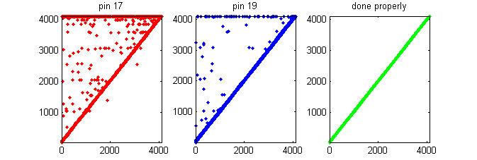
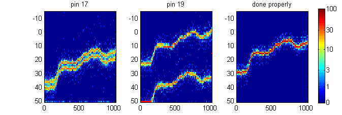
Yes, in the DAC to ADC bead test the bead was directly between the AnalogOut and a AnalogIn pin. The chosen AnalogIn pin needs the capacitor at the pin to digital ground.

In my current test I have modified the DAC to ADC test setup to include a LM324 OpAmp in the pathway. The OpAmp is configured as a non-inverting unity gain amplifier. The unused OpAmps are also configured as unity gain amplifiers. Their postive inputs should be either tied to analog ground or to a source. To maximize possible noise I connected them to the AnalogOut signal.

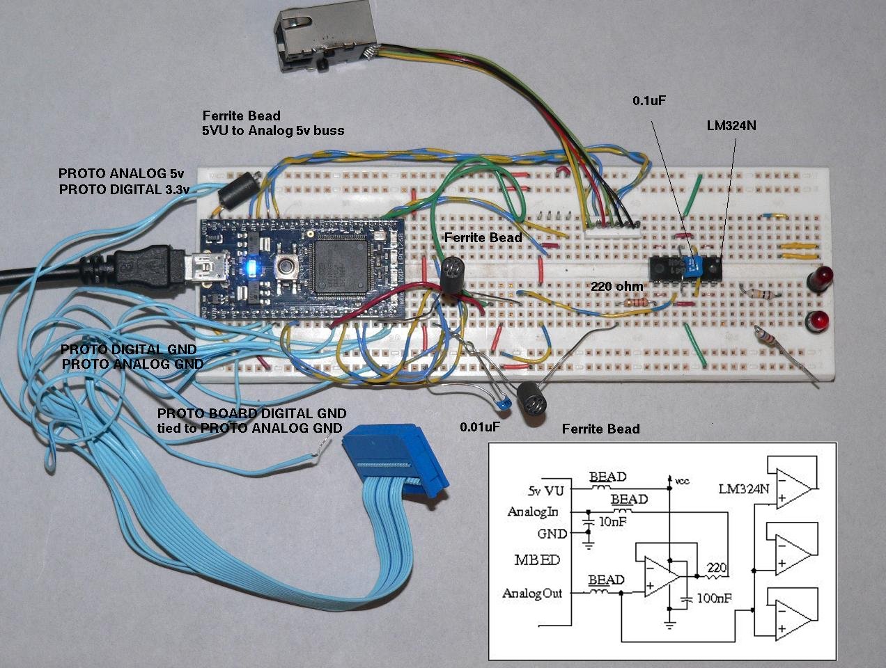
In the following picture you can see my prototype board is a messy layout which should be susceptible to picking up and/or emitting stray signals. The ribbon cable assembly usually goes to my LGCD4531 LCD. The RJ45 MagJack is dangling. Other currently unused leads are still connected.

The LM324 can only drive it's output to within 1.5 volts of its Vcc so to get a full 3.3 volt swing it's Vcc can be tied to a 5v source allowing the output to go to 3.5 volts. Since I am using unity gain on the OpAmp and it's input is coming from the MDED AnalogOUT then the maximum voltage expected is 3.3 volts which is fed back into a MBED AnalogIn. If you add gain, you may need to protect the MBED from overvoltage on the ADC. Remember, although the MBED digital inputs are 5v tolerant, it's analog inputs are not.

In the picture you can see that I derived my Analog 5v source from the MBED VU output on pin 39. I coupled this via a BEAD to the top power rail on the protoboard which I then use as the analog power rail. The bottom powerail is used as the analog ground and is tied back to the digital ground rail on the far left. I did not feel it necessary to couple grounds with a bead.

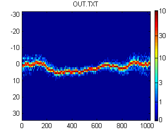
Since the MBED may have an inherent RF noise problem I passed the AnalogOut through a BEAD to reduce conducting that noise to the OpAmps. Notice that I have not really tried to use short leads on the BEADS or the AnalogIn Capacitor. Note the lengths of the wires extending from the MBED to where the LM324 OpAmp actually is.

Also, notice that I tied the AnalogIn capacitor from the chosen AnalogIn pin directly to digital ground. Since the noise being seen at the pin is probably coming from an internal digital pathway that noise needs to be returnd to the digital ground. Connecting the capacitor to analog ground will just pass that noise into the analog ground loop where it can be conducted to the amplifiers. There is a definite noticable difference which ground that capcitor is attached to.


The results I got was virtually noise free. I have forwarded the dump file to Misha for analysis.


-deleted-
13 Dec 2010 . Edited: 13 Dec 2010

Hey guys - I just wanted to throw my testing result in here.  Maybe it can be of some help. 

I have been testing with both the mbed and Keil MCB1700.  Both boards have the same erroneous results using the same code. 

I only found one way to correct this – using the START and DONE bits for acquisition rather than the BURST mode for automatic acquisition (I haven’t tried to use the match condition start mode yet).

It seems that using the burst acquisition mode introduces the large erroneous results (maybe a silicon issue).

Looking at Simons example and Dave’s result the a2d convertor seems to work well using the START and DONE bits.

mbed team – do the api libraries use the BURST mode and return the result when called for or is the START and DONE method used?

*UPDATE*

seems that enabling the peripheral in a ceritan order helps BURST mode

// enable the NVIC vector
NVIC_EnableIRQ(ADC_IRQn);
// clear the START bits
LPC_ADC->ADCR &= ~(0x7 << 24);
// Enable BURST and peripheral
LPC_ADC->ADCR |= ((0x1 << 16) | (0x1 << 21));
// Clear global done isr generation
LPC_ADC->ADINTEN &= ~(0x1 << 0x8);
// enable the channel based on object pin
LPC_ADC->ADINTEN |= (0x1 << a_ch);

This elininated my erroneous results when using BURST mode.


14 Dec 2010


user Thomas Olson wrote:

The results I got was virtually noise free. I have forwarded the dump file to Misha for analysis.


The file looks good, no outliers, single curve in the histogram.

Mischa

14 Dec 2010

user Sam Grove wrote:

Hey guys - I just wanted to throw my testing result in here.  Maybe it can be of some help.

I have been testing with both the mbed and Keil MCB1700. Both boards have the same erroneous results using the same code.

I only found one way to correct this – using the START and DONE bits for acquisition [...]

Looking at Simons example and Dave’s result the a2d convertor seems to work well using the START and DONE bits.

Hi Sam,

Earlier on, I already tried reading the ADC directly as in Simon's example:

dacadcdirectlytodisk

For me it didn't help - the results were no different with this or with the AnalogIn library. Did I miss something?

Best,
Mischa

16 Dec 2010 . Edited: 20 Aug 2011

Hi all,

A first order low pass filter appears to fix the problem. A 6.8k ohm resistor between pin 18 (DAC) and pin 17 (ADC), 220 pF capacitor between pin 17 and pin 1 (gnd).  No bead necessary. The cut-off frequency is 1/(2.pi.R.C)=106 kHz, close to the Nyquist folding frequency corresponding to 200 kHz max. sampling frequency of the ADC. Results:

Horizontal axis: DAC, vertical axis: ADC. y=4*x as expected.

...

Horizontal: DAC, vertical: ADC-4*DAC, color: histogram.

This is well within the specifications.

Best,
Mischa

16 Dec 2010

Great stuff.. So is it a noise/interference problem, or is it the software implementation? Mischa, are the results from your last post using the mbed AnalogIn?

16 Dec 2010

Hi Igor,

So it was an interference problem.  The results are obtained using mbed's AnalogIn, with dacadctodiskshort .

Best,
Mischa

17 Feb 2011

All:

Your thread prompted me to build a tool to explore the phenomenon that you have been discussing. I started a new thread here...

http://mbed.org/forum/mbed/topic/1866/

...because, sadly, I forgot where this thread was. Sorry about that.

23 Jul 2011

Hi, all

I just wanted to give some more data points related to my experience on this problem. The spikes are definitely an internal _hardware_ phenomenon particular to the ADC of the LPC. I've never had any problems before with other ADC's even without worrying to much with analog filtering.

The spikes do seem to be "noise provoked", but are not a measure of the actual noise going into the analog pins.

On a circuit here that had about 5kOhm impedance output going to the ADC, I was able to make the spikes completely disappear by just using a 330pF capacitor between the ADC input and ground. The resulting low-pass filter (5kOhm, 330pF) is still well above the Nyquist frequency at any sampling rate the ADC can support.

23 Jul 2011

I would say the low-pass corner frequency is *right at* the Nyquist frequency for the 200 kHz sampling rate which the ADC can support, rather than well above it?

23 Jul 2011

You are correct. I just did a quick calculation in my head and must have missed something. Thanks for the correction.