LPC4088 QuickStart Board - Getting Started Tour
This section contains a short (and highy recommended) getting started tour to quickly familiarize you with your LPC4088 QuickStart Board. The first four experiments can be performed without any additional hardware.
1. Connect the board to a PC
Connect the HDK USB interface to a PC. A micro-B to A USB cable is needed for this. The HDK USB interface is found on the bottom side of the board under the reset pushbutton (same end of the board where the FPC display connector is located), see picture below.
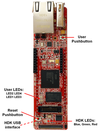
Three LEDs (blue, green, red) will light and after a few seconds of activity, the PC will recognize the LPC4088 QuickStart Board HDK interface as a standard USB drive (see picture below). Please note that the files on this drive are read-only and cannot be modified or removed.
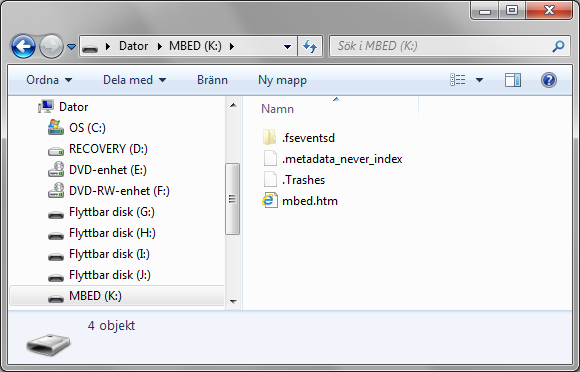
Information
With the current version of the HDK firmware, the mbed.htm file will only lead to a non-existing page on the mbed.org site (giving an error message). On future HDK firmware versions, double-clicking on the mbed.htm file in the new USB drive will take you to the on-line documentation for the board.
2. Register account on mbed.org
You need an mbed account to continue. If you do not have one, signup here and create your account. Otherwise, log in with your normal username and password.
An account gives you access to the on-line compiler. As a first step the LPC4088 QuickStart Board platform should be added to your account. Click on "Platforms" on the toolbar and then select the "EA LPC4088" platform. The page will likely look different since more platforms are continously added.
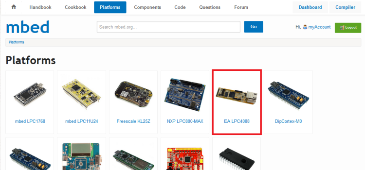
On the page presenting the LPC4088 QuickStart Board, click in "Add to mbed Compiler" button as shown below. The platform is now connected to your account.
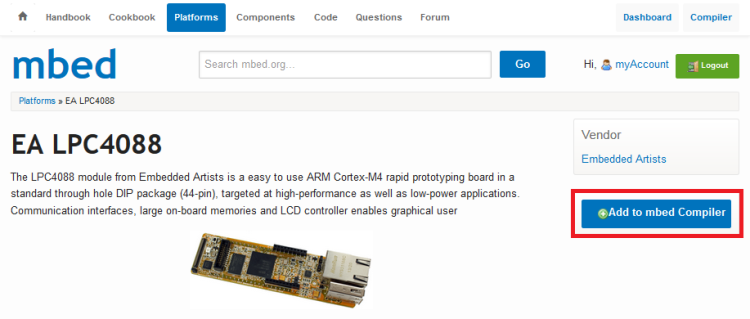
It is possible to add more platforms to you account but for now it is best to have just the LPC4088 QuickStart Board connected.
3. Download applications
The next step is to learn how to download a pre-compiled program.
- The on-line compiler creates a *.bin-file as a result of a successful compilation. Save this binary file to the "MBED" USB drive that is created when connecting your LPC4088 QuickStart Board to your PC. The red HDK LED will flash as the file is copied to the board. To be more specific the content of the binary file is programmed into the LPC4088 flash memory.
When the binary file has been copied the USB drive will shortly disappear from the PC and then come back on. This is because the HDK restarts the USB disk after any operation. - Press the Reset pushbutton
- The program will start to execute. It is a running pattern on the four user LEDs.
Note that the name of the binary file has no meaning. The file is recognized by the bin file ending.
The source code for the pre-compiled program will be investigated in the next step where you learn how to create and compile a program.
The three HDK LEDs have the following meaning:
- Red HDK LED: Flashes when there is activity on the HDK USB drive (when writing a binary file).
- Green HDK LED: Flashes when the CMSIS DAP debug interface is used.
- Blue HDK LED: Flashes when there is serial communication over the virtual USB serial COM channel.
Information
Note that the current HDK firmware version does not support download from Linux or Mac computers. Only from Windows operating system.
Troubleshooting!
Make sure you save the file to the USB disk that was created when connecting the HDK USB interface to your PC. The name of the drive is be MBED. The drive letter will however be different between different PCs.
- If the red HDK LED did not flash when saving the binary file you probably saved it elsewhere!
- Some browsers default to saving files to your "Desktop", so this should be changed; see Choose-where-to-save-files-FAQ
- Some Linux or old Mac PCs don't write data until you "Eject" the drive; see Mounting-with-sync
Don't try and "Open" or "Run" the program files. Always "Save" them to the "MBED" USB disk.
- Some applications (e.g. VLC Media Player) recognize the .bin extension; ignore them!
Make sure you actually start the program!
- Remember to press the Reset pushbutton to start it after you download a new program
- If the binary file has been copied (i.e., downloaded) but nothing happens after pressing the Reset pushbutton, make sure the correct binary file was copied.
When you unplug the USB cable from the HDK USB interface (i.e., disconnect the board from your PC), you may get a "Device Removal" error message; just ignore it. To avoid the message, you can also use "Eject" (Mac) or "Safely Remove Hardware" (Windows).
4. Experiment #1: Create application and compile
The mbed Compiler is an online application used to create your own programs for the LPC4088 QuickStart Board. It translates program source code that you write in to a program binary that the LPC4088 microcontroller can execute. A longer introduction to the online compiler can be found here.
The following six simple steps demonstrate how to create an application, compile it and generate the binary file. The download process was covered in the previous step.
4.1. Open the mbed compiler
Open the online compiler using the link in the site menu (top-right of the page). This will open the Compiler in a new browser tab or window.

4.2. Select LPC4088 platform
Make sure the "EA LPC4088" platform is selected. It should be by default since the "EA LPC4088" platform was the last one added to your account.

If no platform has been selected the position (upper right corner in the compiler window) will display "No device selected". If this is the case or if some other platform is selected, just press on the position. A new window will pop up where it is possible to change selected platform.
4.3. Create a new program
To create a new program in your personal Program Workspace:
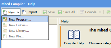
- Click in "New" and select "New Program..."
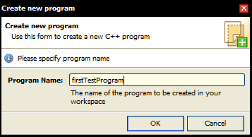
- Enter the name of the new program (e.g. "firstTestProgram"), and click "OK"
- Your new program folder will be created under "My Programs".
4.4. View the default program source code
Click on the "main.cpp" file in your new program to open it in the file editor window. This is the main source code file in your program, and by default it contains a simple LED flashing program already. The code should look like:
main.cpp
#include "mbed.h"

DigitalOut myled(LED1);

int main() {
    while(1) {
        myled = 1;
        wait(0.2);
        myled = 0;
        wait(0.2);
    }
}
4.5. Compile and Download the program
To compile the program, click the Compile button in the toolbar. This will compile all the program source code files within the program folder to create a binary program.
- After a successful compile, you will get a "Success!" message in the compiler output and the download dialog will pop up. Save it to the location of the "MBED" USB disk, and then press the Reset pushbutton on the board to start it!
- The red HDK LED will flash while downloading the binary file.
- If there are errors, they will show up in the "Compiler Output" window, and will need to be fixed!
- Note that the two blue LEDs (LED3 and LED4) will light weakly. This is because the controlling pins are inputs per default and the pull-up resistors in the LPC4088 pin will turn the LEDs on weakly.
Troubleshooting!
- Some web browsers and download managers will automatically download files to a predefined location. To configure the download location so you can save it to the "MBED" USB disk, see Choose-where-to-save-files-FAQ
- The compiler only supports some web browsers and platforms; see Which-browsers-are-supported-FAQ
- If you have problems using cut and paste functionality (Ctrl+C, Ctrl+V) in IE7, see Cut-and-paste-IE-FAQ
4.6. Change program and Recompile
After this simple first program, lets test something more complex and control all four LEDs in a running pattern. Update the code in main.cpp as below. Compile, download and verify the effect.
main.cpp
#include "mbed.h"

DigitalOut myled1(LED1);
DigitalOut myled2(LED2);
DigitalOut myled3(LED3);
DigitalOut myled4(LED4);

int main() {
    //Turn all LEDs off
    myled1 = 1;  //LED1 is active low, turn it off
    myled2 = 1;  //LED2 is active low, turn it off
    myled3 = 0;  //LED3 is active high, turn it off
    myled4 = 0;  //LED4 is active high, turn it off

    //Enter forever loop
    while(1) {
        myled3 = 0;  //Turn LED3 off
        myled1 = 0;  //Turn LED1 on
        wait(0.2);   //Wait 200 ms
        myled1 = 1;  //Turn LED1 off
        myled2 = 0;  //Turn LED2 on
        wait(0.2);   //Wait 200 ms
        myled2 = 1;  //Turn LED2 off
        myled4 = 1;  //Turn LED4 on
        wait(0.2);   //Wait 200 ms
        myled4 = 0;  //Turn LED4 off
        myled3 = 1;  //Turn LED3 on
        wait(0.2);   //Wait 200 ms
    }
}
Note that LED1 and LED2 are active low meaning that they will turn on when the respective LPC4088 pin is low. LED3 and LED4 have the opposite polarity They are active high and the LEDs will turn on when the LPC4088 pin is high.
Experiment with more LED flash patterns!
Try to recreate the flash pattern in the pre-compiled test binary in step 3.
More information about the wait()-function can be found here. There are also wait_ms() and wait_us() functions.
5. Experiment #2: Timer
The programs in the previous step were controlled by delays. There are more sophisticated ways to control the LED flashing, for example by using the mbed ticker functionality. More information can be found here. The ticker functionality is a prime example of the powerful mbed framework. Advanced functionality can quickly be incorporated into your application by just instantiating an object.
Test the code below and experiment with different flash patterns.
main.cpp
#include "mbed.h"

Ticker tickObject;
DigitalOut myled1(LED1);
DigitalOut myled2(LED2);
DigitalOut myled3(LED3);
DigitalOut myled4(LED4);

void flashHandler(void) {
    static int ledState = 0;

    //Turn all LEDs off
    myled1 = 1;
    myled2 = 1;
    myled3 = 0;
    myled4 = 0;

    switch (ledState) {
        case 0: myled1 = 0;  break; //Turn LED1 on
        case 1: myled2 = 0;  break; //Turn LED2 on
        case 2: myled3 = 1;  break; //Turn LED3 on
        case 3: myled4 = 1;  break; //Turn LED4 on
        default: ledState = 0;
    }
    ledState++;
    if (ledState >= 4)
        ledState = 0;
}

int main() {
    //Turn all LEDs off
    myled1 = 1;  //LED1 is active low, turn it off
    myled2 = 1;  //LED2 is active low, turn it off
    myled3 = 0;  //LED3 is active high, turn it off
    myled4 = 0;  //LED4 is active high, turn it off

    tickObject.attach(&flashHandler, 0.2);    //Repeatedly call flashHandler(), once each 200ms

    //Enter forever loop
    while(1) {
        ;    //do something useful while LED flashing is handled in the background
    }
}
There is also a timeout functionality that can be used, for example if varying time intervals are needed between calling flashHandler(). The timeout must then restart after every call to flashHandler().
6. Experiment #3: Pushbutton
There is a user pushbutton on the board. See top picture on this page for locating the pushbutton. It is on the opposite end of the board from the reset pushbutton.
The user pushbutton can short pin 23 (LPC4088 pin P2.10) to ground allowing the pin to be sampled low when the button is pressed. Note that the pullup resistor on pin 23 must be enabled. Else the pin will not sample high when the pushbutton is not read. See example code below for how that is accomplished.
Information
If the user pushbutton is pressed while power cycling the board the LPC4088 microcontroller will enter ISP mode. The program that is possibly already loaded into flash will not start executing. However, it is still possible to download programs via HDK USB drag-n-drop.
Below is a naive implementation where the user pushbutton is supposed to advance the flash pattern one step every time the button is pressed... but in reality a four state random generator is created. Test and verify for yourself.
main.cpp
#include "mbed.h"

DigitalIn myButton(p23);  //p23 is pin P2.10 on the LPC4088 and has the user pushbutton connected to it
DigitalOut myled1(LED1);
DigitalOut myled2(LED2);
DigitalOut myled3(LED3);
DigitalOut myled4(LED4);

int main() {
    //Turn all LEDs off
    myled1 = 1;  //LED1 is active low, turn it off
    myled2 = 1;  //LED2 is active low, turn it off
    myled3 = 0;  //LED3 is active high, turn it off
    myled4 = 0;  //LED4 is active high, turn it off

    myButton.mode(PullUp);    //enable pullup resistor on input

    //Enter forever loop
    while(1) {
        myled3 = 0;  //Turn LED3 off
        myled1 = 0;  //Turn LED1 on
        while (myButton);   //Wait until button pressed
        myled1 = 1;  //Turn LED1 off
        myled2 = 0;  //Turn LED2 on
        while (myButton);   //Wait until button pressed
        myled2 = 1;  //Turn LED2 off
        myled4 = 1;  //Turn LED4 on
        while (myButton);   //Wait until button pressed
        myled4 = 0;  //Turn LED4 off
        myled3 = 1;  //Turn LED3 on
        while (myButton);   //Wait until button pressed
    }
}
The code must be updated so that every time the program wait for a button press it must not only wait for the press but also for the release. Hint: while (!myButton); will wait for the button to be released.
7. Experiment #4: UART and HDK
The HDK has functionality to communicate with the PC through a "USB Virtual Serial Port" over the same USB cable that is used for programming. To begin with, a USB driver is needed for this. Follow the installation details here. The page also contains information about how to make use of the serial channel.
The example program below demonstrates usage.
main.cpp
#include "mbed.h"

Serial pc(USBTX, USBRX);  //serial channel over HDK USB interface
Ticker tickObject;
DigitalOut myled3(LED3);
DigitalOut myled4(LED4);
DigitalIn myButton(p23);  //p23 is pin P2.10 on the LPC4088 and has the user pushbutton connected to it

void flashHandler(void) {
    static int ledState = 0;

    //Turn both LEDs off
    myled3 = 0;
    myled4 = 0;

    switch (ledState) {
        case 0: myled3 = 1;  break; //Turn LED3 on
        case 1: myled4 = 1;  break; //Turn LED4 on
        default: ledState = 0;
    }
    ledState++;
    if (ledState >= 2)
        ledState = 0;
}

int main() {
    //Turn all LEDs off
    myled3 = 0;  //LED3 is active high, turn it off
    myled4 = 0;  //LED4 is active high, turn it off

    myButton.mode(PullUp);    //enable pullup resistor on input

    tickObject.attach(&flashHandler, 0.2);    //Repeatedly call flashHandler(), once each 200ms

    //Enter forever loop
    pc.printf("Ok, so now we are entering the forever loop...\n");
    while(1) {
        //check if user button pressed
        if (myButton == 0) {
            pc.printf("Button pressed!\n");
            while (!myButton);  //wait until button released
            wait_ms(10);  //add short delay to handle pushbutton contact bounce
        }
    }
}
See the Serial communication with a PC handbook page for more details about how to for example receive characters from the PC.
Information
Note that the blue HDK LED flash every time characters are transferrer over the USB virtual serial port.
8. Experiment #5: XBee interface
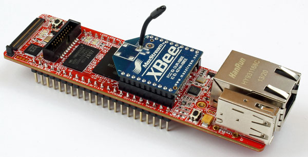
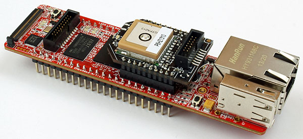
One innovative feature of the LPC4088 QuickStart board is the RF module interface that build on the XBee standard. There are many different RF modules compatible to this standard, including Embedded Artists GPS Receiver Module and the RN-XV module by Roving Networks.
XBee Series 1 connected to the LPC4088 QuickStart Board
Import programapp_xbee_s1
An example that shows how to use the XBee class/interface
GPS Receiver board connected to the LPC4088 QuickStart Board
Import programapp_gps
Example using the MTK3339 (GPS) library.
9. Experiment #6: Breadboard + RGB-LEDs
To be completed...
10. Experiment #7: Graphical applications
The LPC4088 QuickStart Board is really suitable to use for graphical applications. There is a Base Board available which makes it easy to connect the LPC4088 QuickStart Board to a number of different display options. The picture below shows a 7 inch display connected to the board.
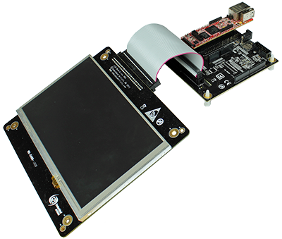
There are several applications available which lets you test graphics.
- Test the application which is based on Adafruit's GFX library
Import programapp_gfx
Example using the GFX graphical library, EaLcdBoard, TSC2046 touch screen and SDRAM initialization
- Visit the Projects page where a number of graphic demos are available.
- To use a more professional graphical library visit the emWin GUI page. This page describes how to import and use Segger's emWin library.
10 comments on LPC4088 QuickStart Board - Getting Started Tour:
Please log in to post comments.


4088 Start-up Problems
I am excited about the M4 on the 4088 QuickStart Board. After purchasing one, I figured to get going all there was to do was plug it. BUT...
After plugging in the board at the HDK USB interface, LED's on the board flash about 4 times, once a second, and the PC (running Windows 8.1) beeps at the same time. Eventually the flashing/beeping stops, with 4 LED's on solidly: HDK LED's blue, red and green, and User LED3.
Most importantly, there is no MBED USB drive visible in the PC flie system.
Turns out, I purchased two 4088 boards. The same thing happens with the second board. What should I do???