Roll your own KL25Z boards...
I drew these up in order to prototype for a project I'm working on while I work out the kinks on the various sub-systems of the board. Use these to build your own KL25Z boards for those projects where you need a multitude of boards but don't want to plunk down $13 each for the FRDM-KL25Z and have all the extra stuff that you won't necessarily use.
Some brief blog postings about them here, here, and here.
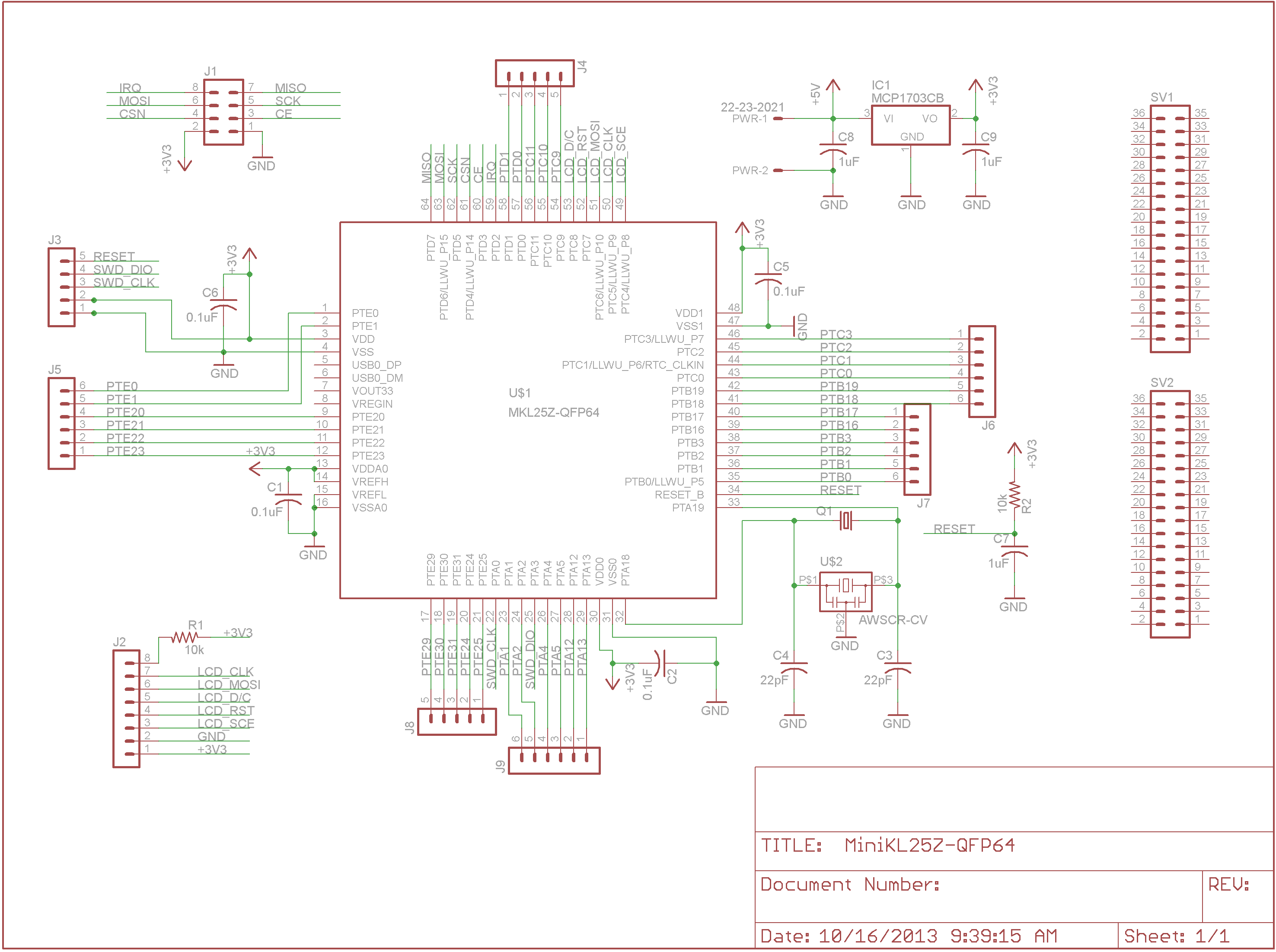
It should be noted that although I've drawn a crystal/resonator into the MiniKL25Z, I did not actually include those in the board I built up. After I'd sent the board off, I discovered that the internal oscillator can be used to run the KL25Z at 48MHz if the accuracy of a crystal is not required. I've also modified the mbed source for the KL25Z so that the default option is to run off the internal oscillator and fixed the speed so that it'd be 48MHz instead of the original 41MHz. See the library here: http://mbed.org/users/icenyne/code/mbed-src-FLL48/.
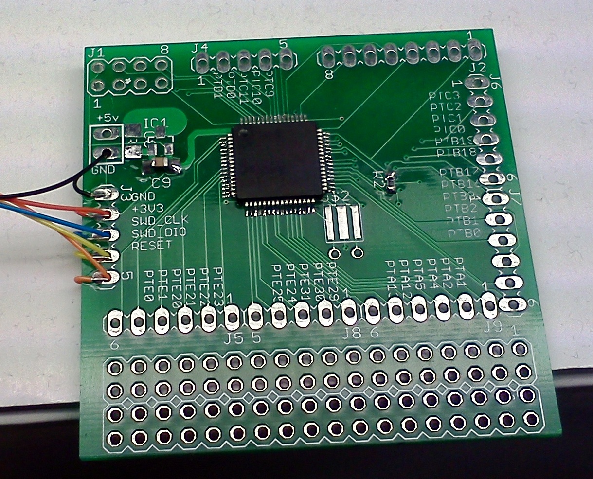
Boards may be ordered via the links included below from OSH Park. I really like the purple boards - they're just like the images...
No OpenSDA programmer was included on the board because these were intended for prototyping and/or use in an embedded application (all boxed up single purpose use, one the application code is fully developed). I'm using a FRDM-KL25Z to program these but a McHck could just as easily be used.
MiniKL25Z board:
Order boards here

 MiniKL25Z board design files: /media/uploads/icenyne/minikl25z-64qfp.zip
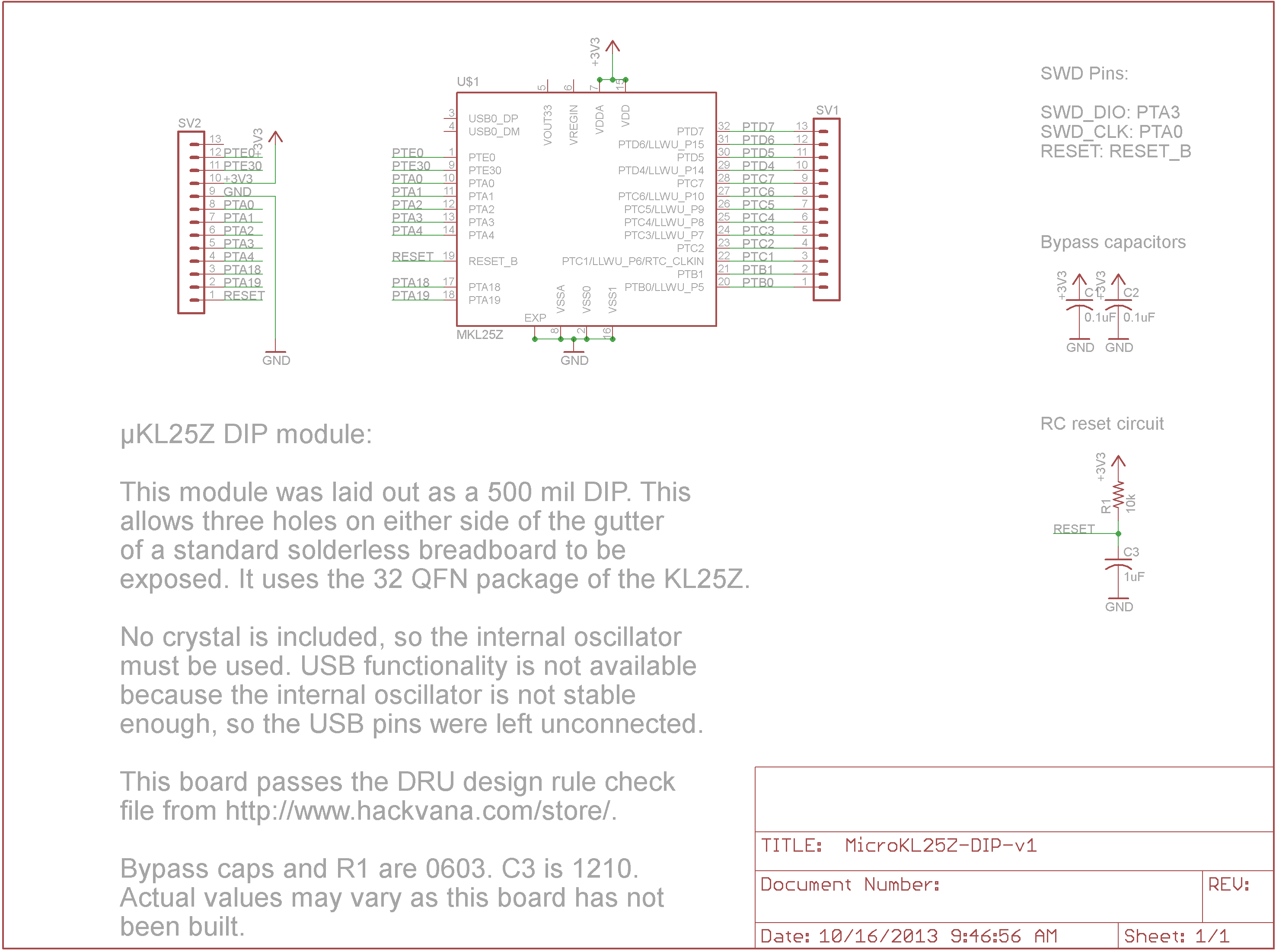
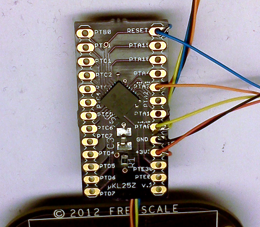
MicroKL25Z:
Order boards here

 MicroKL25Z board design files: /media/uploads/icenyne/microkl25z-dip.zip
12 comments on Roll your own KL25Z boards...:
Hello,
nice looking boards, appreciate that you are also sharing board design files! Will definitely help some people.
What I wonder, why did you modify mbed-src? You can create a library which would change clocks and then call SystemCoreClockUpdate.
Regards,
0xc0170
What I wonder, why did you modify mbed-src? You can create a library which would change clocks and then call SystemCoreClockUpdate.
The long and short answer is that's what you get when a hardware guy plays software engineer...
There's undoubtedly a better, more efficient, preferred way to do it, but not having done much coding or understanding the guidance I was given, I did what worked. I wasn't sure how to use/call SystemCoreClockUpdate (I think you may have given that advice before).
I dug into the mbed source and saw that there were three clocking options built in. So I just modified the source to choose the FLL option by default, and then I modified it further so that it'd run at 48MHz instead of the default 41MHz. Admittedly brute force, but it works...
Actually, after pondering the question some more, I really did need to modify the source. The reason being that the boards I made have no crystal on them.
The binary mbed library will not work because it enables the PLL with the external crystal when it starts up. User code cannot change anything until after this is done, so the process described above can never be executed. I thought my QFN board was dead until I realized this (I expected it with the QFP board but forgot in my haste and excitement with the QFN one). Once I swapped in my modified mbed-src library, it came right up.
Since three clocking options were included within the mbed source, it should be no less a valid means of modifying the default clocking configuration than modifying the clock settings in the user code and then running SystemCoreClockUpdate.
Hi! Can I use a J-link SWD to program these? :D
And how did you program them using the KL25z boards.
I'm sorry I'm a bit fairly new to ARM development. Please bear with me :D
If the J-link SWD programmer does what the K20 does on the FRDM-KL25Z, then sure, you should be able to use it. I'm not familiar with that particular tool, so I don't know for sure. But then, the whole point of SWD is a common protocol for programming these type devices.
To use the FRDM-KL25Z, I cut the J11 trace on the bottom of the board. This disconnects the SWD_IO line between the KL25Z and the K20, which keeps the on-board KL25Z from responding to anything the K20 sends at it. Then connect 5 wires to SWD connector J6 on the KL25Z to my boards: +3.3V, ground, RESET, SWD_IO, and SWD_CLK. You can see the wires connecting the two boards in the photos above. The more graceful solution would have been to put the mating header connection on my boards and get the headers and flexible cables for connecting them but I was more interested in getting boards to play with.
The QFNs are difficult to hand solder - in fact, one really needs a hot air SMT rework tool because an iron tip is not fine enough to reach down in the crevasse between the side of the package and the solder pads on the board. The QFP is fairly simple with a fine tipped iron and a microscope.
Thank you! :)
Hi !
Thank you for sharing it ! Just a question : how do you change the default bootloader to the mbed bootloader with only SWD ?
As I understand it, the MBED boot loader firmware resides in the K20 device on the FRDM-KL25Z board. That firmware implements the removable flash drive on the host computer and then transfers the bin file dropped on it to the KL25Z via the SWD serial programming protocol. SWD is a serial JTAG-like hardware debugging port/protocol.
The KL25Z on the boards above can be used with any SWD compatible programmer, MBED or otherwise.
I have a modified Mbed-src library that will enable this board to run with a 32kHz crystal with two 12pf capacitors. This will enable the RTC function to be used without external 32kHz clock input from the SDA MCU. The core runs at 48Mhz (47.97Mhz) @ around 6mA and gives a far greater clock accuracy and stability than the IRC. It also does not interrupt the RTC clocking during reset, only a power cycle resets the RTC registers.
I have been running this configuration for some time now and find I no longer need a separate RTC module.
It can be found here:
http://mbed.org/users/star297/code/KL25Z-32kHz-crystal-mbed-src-library/
You can also select the other three clock set ups that mbed have now correctly defined including the 4Mhz IRC if needed (gives 48Mhz core clock (47.97Mhz).
Hello,
Congratulations on your work, which I have just discovered.
I'm looking to do the same thing as you, using only the KL25Z128VLK4 chip.
I have followed your schematics (using the pins of my QFP80 chip). I use the SWD of my FRDMKL25Z platform to program the chip but after several hours of testing it does not work... I use an external 8 Mhz osciallteur like on the original platform.
After reading the oscilloscope, there is no oscillation at the quartz terminal... I'm not sure if it's a good idea to use the same chip as the original one, but I'm not sure if it's a good idea to use the same chip as the original one.
I'm using original chips, I put decoupling capacitors for everything, test each pin and their power supply...
I need help, thanks in advance
Here is the original schematic
Please log in to post comments.

 MiniKL25Z board design files: /media/uploads/icenyne/minikl25z-64qfp.zip
 MicroKL25Z board design files: /media/uploads/icenyne/microkl25z-dip.zip


Hello,
nice looking boards, appreciate that you are also sharing board design files! Will definitely help some people.
What I wonder, why did you modify mbed-src? You can create a library which would change clocks and then call SystemCoreClockUpdate.
Regards,
0xc0170