ScottROV1
Here is a summary of sorts, as it stands today 2 September 2011:
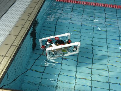
My "individual project" for the third year of my electronic engineering course is an underwater ROV (remotely operated vehicle). This means it moves around underwater but is controlled from out of the water by an operator. The operator uses the "top" controller which has 2 joysticks, some switches and a video screen. The top controller sends control instructions to the "bottom" controller located on the ROV via a cable known as a "tether".
The tether is made up of a power cable (I'm using some speaker cable with 2 x 2.5 mm squared CSA (cross sectional area), and a data cable (I am using an ethernet cable which has 4 twisted pairs).
The control instructions are simply to turn the individual motors on or off, or switch instructions eg lights on or off.
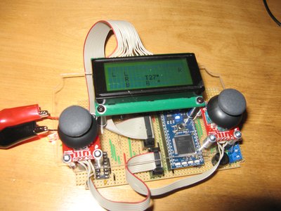
On the top controller I am using an mbed which is connected to the two joysticks, three switches, an LCD display screen, a temperature sensor, some status LED's, and a warning buzzer (for leak alarms).
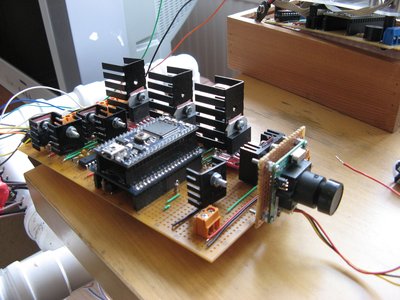
On the bottom controller I am using another mbed that will connect to the 7 thruster motors, another temperature sensor, leak detectors, and an IMU board. There is also a video camera.
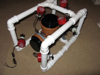
I am using 7 thrusters for a variety of reasons. I am using 4 for horizontal movement, and 3 for vertical movement.
For horizontal movement I am using 4 thrusters that are placed at a 45 degree angle to the frame. By turning on any two at a time I get forward, reverse, spin left, spin right, pan left, and pan right. I could also use the minimum configuration of 3 with one horizontal on the left and one horizontal on the right to go forward and backwards and spin around, and one horizontal at 90 degrees to pan left and right. I decided the four thruster combination would be better as it is simpler wiring (uni-directional motor control rather than bi-directional) and that the symmetrical arrangement with counter-rotating propellers would minimise any twist caused by a single pan left/right thruster.
For vertical control I am planning to use 3 bi-directional thrusters. There will be one on either side, and one at the rear. But why three instead of one? When initially describing this project to my course leader he thought that with a single vertical thruster the project was too easy so I came up with a more complicated project: include a control system.
Control systems are fascinating to me. CNC routers and cutters that I sold for 15 years all use control systems for accurate positioning. So I decided I would add a self-levelling control system to my ROV. Imagine I have a gripper arm at the front (which I won't at least initially). If it picks up something, the centre of gravity and centre of buoyancy change and the ROV will tilt forward. This means trying to control it accurately will be very difficult - unless it has an inbuilt stability system - one that self-levels it by adjusting power to the three vertical thrusters!
I am planning to use an IMU (an inertial measurement unit) to sense the tilt level. I have purchased one from another mbed developer that was designed for autonomous flying. It has a 3 axis accelerometer, a 3 axis gyro, and a 3 axis magnetometer. I don't think I need all that but I have it on the board (http://mbed.org/users/atommota/notebook/imu-daughterboard/). It simply plugs into the mbed and is the same size.
For the thrusters I am following these instructions: http://www.homebuiltrovs.com/howtobilgeconversion.html
Now, as expected, the project so far has been a series of challenges to overcome, with more presenting themselves every day. Yesterday I got a motor running under mbed / MOSFET control, with PWM, which was an important step along the way for me.
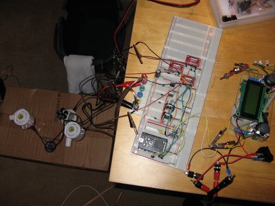
One of today's challenges is to work on the data comms between the top and bottom controllers. I have got the two mbeds communicating with each other when separated by short wires. I then used the 30m data wire and the comms were still fine, but they shared the same ground, so I then tried with their grounds also separated by the 30m. This also worked fine, but with no motors running (and no current draw) there was virtually no voltage drop across the tether so the grounds were basically the same.
The next step today is to test the comms whilst a motor is running (I can only run one motor at a time til I get my next delivery of parts). With only one motor running there should be a voltage drop of about 2V across the tether so we'll see if that effects the comms. If it does I'll need to look into RS232 or RS485 systems which I think sort of add a layer on top of what I am using at the moment, which is simply UART to UART.
One of the biggest challenges is to create a watertight enclosure for the electronics. I don't have any real access to machining resources, and my budget is very limited, so I am planning to use 110mm diameter underground drainage pipe and fittings. This is a relatively cheap option (but will still cost around £50). My original goal was to aim for a 30m maximum depth but I think now I will simply try for 5m (the depth of the local diving pool) and when I get some money later I'll get a proper pressure vessel manufactured from acrylic / aluminium / stainless steel.
Anyway, there's some information for you. Any questions?
12 comments on ScottROV1:
Please log in to post comments.

Interesting project. I'm looking forward to how it all works out.
Keep us updated!