Using a Speaker for Audio Output
Many embedded devices need audio output for user feedback. The techniques and sounds used vary quite a bit as seen in the video below about designing sound feedback for cars. Several examples will be provided with the mbed APIs using both PWM and AnalogOut with some additional low cost parts.
A recent CBS News story on engineers designing car feedback sounds
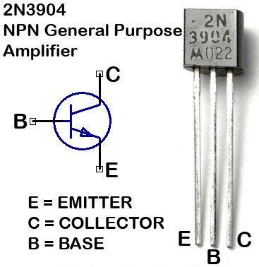
With just a small low cost speaker and a 2N3904 driver transistor is it possible to generate simple sound effects on mbed for under $2. Hooking up the speaker directly to an mbed output pin results in very low volume and a driver circuit is needed to boost the current levels to drive the speaker to provide adequate volume levels. Small piezo speakers will respond to a very limited audio frequency range without a driver, but the volume is still relatively low and is often only of use at the resonant frequency listed in the datasheet. The demo code will use a PWM output pin and then the AnalogOut pin. PWM output pins have a bit more drive current than the AnalogOut pin. The volume is even lower on the AnalogOut pin without a driver. A lot of this volume difference is due to the fact the square waves sound louder to humans than sine waves at low frequencies.
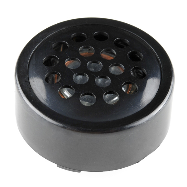
Sparkfun PCB or breadboard mount Speaker 8ohm .1W
Warning
The small Sparkfun PCB speaker works great in a breadboard and is very handy, but when removing it from a breadboard be careful to pry the bottom up first with something flat like a screwdriver. If you pull it out hard using the top black metal speaker cover, the PCB on the back cover can pull off and break the tiny speaker wires soldered to the pins inside the back cover.
Wiring
Solder one end of two long jumper wires to the speaker's terminals for easy breadboard hookup. With the small PCB mount speaker from Sparkfun seen earlier, soldering is not required as its pins will plug into a breadboard. Next, hook up the speaker and 2N3904 transistor as shown in the typical driver circuit below. The speaker is the load. For VCC, use VU or Vout. Be sure to double check the orientation of the three transistor pins in the schematic below and the images above, if it is not correct it will not work! The part number seen in the transistor photo above is on the flat side of the transistor case. For a quick breadboard demo, you can leave out the (around 1K) resistor if you do not have one (just connect the digital control signal jumper wire directly to transistor base) and a diode is not needed. The first demo uses mbed p21 for the digital control signal.
Be careful when removing the Sparkfun PCB mount style speaker from the breadboard. The black plastic case top can pull off along with the tiny speaker wires, so get underneath to the PCB a bit to pry it up.
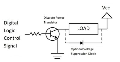
A typical driver circuit for digital outputs
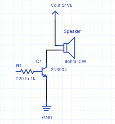
Speaker driver circuit used for mbed audio demos
Using PWM hardware to generate a simple audio tone
The simplest way to generate an audio signal to play on the speaker is to use a hardware PWM output. Set the PWM period to 1/frequency of the desired sound. The PWM duty cycle is set to 0.5. A lower duty cycle setting produces lower volume, but keep in mind that since square waves or pulses are generated there will also be a lot of higher frequency harmonics produced. Not quite a pure tone, but then again most instruments also generate some harmonics. At higher audio frequencies (above a couple thousand hertz) it also becomes harder for humans to hear the difference between a square wave and a sine wave. The advantage of using the PWM hardware is that it takes minimal memory and no processor time to output an audio tone. If only a beep, click, or siren alarm sound is needed this may be the appropriate choice.
#include "mbed.h"
// speaker sound effect demo using PWM hardware output
PwmOut speaker(p21);

int main()
{
    int i;
// generate a 500Hz tone using PWM hardware output
    speaker.period(1.0/500.0); // 500hz period
    speaker =0.5; //50% duty cycle - max volume
    wait(3);
    speaker=0.0; // turn off audio
    wait(2);

// generate a short 150Hz tone using PWM hardware output
// something like this can be used for a button click effect for feedback
    for (i=0; i<10; i++) {
        speaker.period(1.0/150.0); // 500hz period
        speaker =0.25; //25% duty cycle - mid range volume
        wait(.02);
        speaker=0.0; // turn off audio
        wait(0.5);
    }

// sweep up in frequency by changing the PWM period
    for (i=0; i<8000; i=i+100) {
        speaker.period(1.0/float(i));
        speaker=0.25;
        wait(.1);
    }
    wait(2);

// two tone police siren effect -  two periods or two frequencies
// increase volume - by changing the PWM duty cycle
    for (i=0; i<26; i=i+2) {
        speaker.period(1.0/969.0);
        speaker = float(i)/50.0;
        wait(.5);
        speaker.period(1.0/800.0);
        wait(.5);
    }
// decrease volume
    for (i=25; i>=0; i=i-2) {
        speaker.period(1.0/969.0);
        speaker = float(i)/50.0;
        wait(.5);
        speaker.period(1.0/800.0);
        wait(.5);
    }
    speaker =0.0;
    wait(2);

}
A new C++ class to play a note using PWM
Based on the previous example, a new class can be developed to play a note on a speaker using PWM. The obvious three arguments are the frequency, the time duration of the note, and the volume level. The Speaker class in this demo uses the existing PwmOut class and uses these three arguments in the PlayNote(frequency, duration, volume) member function. To be consistent with other mbed APIs, the volume argument will range from 0.0…1.0. The earlier euro police siren is used in the test program. Songs can also be played, if you have the notes and durations available. For the musical note frequencies, see http://en.wikipedia.org/wiki/Piano_key_frequencies
#include "mbed.h"
// new class to play a note on Speaker based on PwmOut class
class Speaker
{
public:
    Speaker(PinName pin) : _pin(pin) {
// _pin(pin) means pass pin to the Speaker Constructor
    }
// class method to play a note based on PwmOut class
    void PlayNote(float frequency, float duration, float volume) {
        _pin.period(1.0/frequency);
        _pin = volume/2.0;
        wait(duration);
        _pin = 0.0;
    }

private:
// sets up specified pin for PWM using PwmOut class
    PwmOut _pin;
};

// Speaker test program - earlier euro police style siren now using new class method
//
// can also be used to play a song, if you have the notes and durations
// for musical note frequencies see http://en.wikipedia.org/wiki/Piano_key_frequencies
int main()
{
// setup instance of new Speaker class, mySpeaker using pin 21
// the pin must be a PWM output pin
    Speaker mySpeaker(p21);
    // loops forever playing two notes on speaker
    while(1) {
        mySpeaker.PlayNote(969.0, 0.5, 0.5);
        mySpeaker.PlayNote(800.0, 0.5, 0.5);
    }
}
Here is a version with a complete demo project setup and the class definition moved to a *.h file
Import programspeaker_demo_PWM
Demo for new class to play a note on a speaker using a PWM output See http://mbed.org/users/4180_1/notebook/using-a-speaker-for-audio-output/
Playing a Song with PWM using Timer Interrupts
The previous speaker class example does not return from PlayNote() until the note ends. If an application needs to play a sound or a long sequence of notes (i.e., a song) and continue to execute other code, a timer interrupt can be used so that the call returns immediately and the song continues to play using timer interrupts while other code can execute in main. The new SongPlayer class in this example program sets up the timer with the Timeout API and plays a song passed to it in two arrays. The note array contains the frequency and a duration array that contains the duration of each note. The example uses p26 for the speaker PWM output. The song plays while the LED flashes back in main. The class in SongPlayer.h sets up the timer interrupt for the next note's duration and sends the new note frequency data to the PWM hardware. A note with a 0 duration ends the song. If long songs are used, making the arrays "const" will save RAM by putting the data in flash.
#include "mbed.h"
#include "SongPlayer.h"

// Song test program - plays a song using PWM and timer interrupts
// for documentation see http://mbed.org/users/4180_1/notebook/using-a-speaker-for-audio-output/
// can be used to play a song, if you have the notes and durations
// for musical note frequencies see http://en.wikipedia.org/wiki/Piano_key_frequencies

//Set up notes and durations for sample song to play
// A 0.0 duration note at end terminates song play
float note[18]= {1568.0,1396.9,1244.5,1244.5,1396.9,1568.0,1568.0,1568.0,1396.9,
                 1244.5,1396.9,1568.0,1396.9,1244.5,1174.7,1244.5,1244.5, 0.0
                };
float duration[18]= {0.48,0.24,0.72,0.48,0.24,0.48,0.24,0.24,0.24,
                     0.24,0.24,0.24,0.24,0.48,0.24,0.48,0.48, 0.0
                    };

DigitalOut led1(LED1);
int main()
{
// setup instance of new SongPlayer class, mySpeaker using pin 26
// the pin must be a PWM output pin
    SongPlayer mySpeaker(p26);
// Start song and return once playing starts
    mySpeaker.PlaySong(note,duration);
    // loops forever while song continues to play to end using interrupts
    while(1) {
        led1 = !led1;
        wait(.1);
    }
}
Import programsong_demo_PWM
Plays a song using PWM and timer interrupts. Returns once song starts.
This demo was run on the mbed application board. It has a small on-board PWM connected speaker on P26. Notice in the video below that the song plays while the main program continues to blink the LED.
Using the DA with AnalogOut
A second approach would be to use mbed's Analog output pin (AnalogOut - p18). Samples of the audio signal could be constantly output to the D/A hardware to produce the audio signal. Several samples are needed at the highest frequency, in theory only two samples at the highest frequency with an ideal low pass filter. In practice, a higher sample rate is probably needed for high Audio quality. This demo does not even have the low pass filter and 128 samples of a sine wave cycle are precomputed and output using timer interrupts. The timer interrupt period is setup so that a 500Hz tone is produced. This generates a fairly accurate sine wave and produces a pure tone with very few harmonics (compared to the earlier square wave). The disadvantage is that large memory buffers would be needed for complex sounds and the processor must constantly be available to respond to interrupts and output the next sample. Move the driver input pin to p18 for the analog demo code.
#include "mbed.h"
// Audio output demo for speaker
// generates a 500Hz sine wave on the analog output pin
// 128 data points on one sine wave cycle are precomputed,
// scaled, stored in an array and
// continuously output to the Digital to Analog convertor

AnalogOut DAC(p18);
//global variables used by interrupt routine
volatile int i=0;
float Analog_out_data[128];

// Interrupt routine
// used to output next analog sample whenever a timer interrupt occurs
void Sample_timer_interrupt(void)
{
    // send next analog sample out to D to A
    DAC = Analog_out_data[i];
    // increment pointer and wrap around back to 0 at 128
    i = (i+1) & 0x07F;
}

int main()
{
    // set up a timer to be used for sample rate interrupts
    Ticker Sample_Period;
    // precompute 128 sample points on one sine wave cycle
    // used for continuous sine wave output later
    for(int k=0; k<128; k++) {
        Analog_out_data[k]=((1.0 + sin((float(k)/128.0*6.28318530717959)))/2.0);
        // scale the sine wave from 0.0 to 1.0 - as needed for AnalogOut arg
    }
    // turn on timer interrupts to start sine wave output
    // sample rate is 500Hz with 128 samples per cycle on sine wave
    Sample_Period.attach(&Sample_timer_interrupt, 1.0/(500.0*128));
    // everything else needed is already being done by the interrupt routine
    while(1) {}
}
A new C++ class to play a note using analog out
The next step is to develop a class and move the Speaker class definition to a *.h file. The example above only works to around 3000 hz, so 32 samples per cycle is used in the class and scaled integer values are sent to the D/A to speed things up a bit. This version runs to just a bit above 5000 hz which is 5000*32 or 160,000 interrupts per second. 5000 hz sounds a bit low, but the highest frequency on a piano key is around 4100 hz. Frequencies above 5000 will crash mbed (LPC1768) as interrupts occur faster than the interrupt routine's execution time. All of the implementation details including the data samples and the interrupt routine are hidden inside the class Speaker.h file. The same class member function is provided as before in the PWM Speaker class, PlayNote(frequency, duration, volume). So the main program is simple as seen below.
#include "mbed.h"
#include  "Speaker.h"

int main()
{
// setup instance of new Speaker class, mySpeaker
// the pin must be the AnalogOut pin - p18
    Speaker mySpeaker(p18);
    // loops forever playing two notes on speaker using analog samples
    while(1) {
        mySpeaker.PlayNote(969.0, 0.5, 1.0);
        mySpeaker.PlayNote(800.0, 0.5, 1.0);
    }
}
Use the import program link below to get the complete demo project with the required Speaker.h file.
Import programspeaker_demo_Analog
A class to play notes on a speaker using analog out See https://mbed.org/users/4180_1/notebook/using-a-speaker-for-audio-output/
A Class D Audio output
The third approach is almost identical to the previous analog example, but PWM hardware is used instead of a Digital to Analog convertor. PWM is more energy efficient than analog since a completely on or off transistor dissipates less energy as heat. This approach is used in many current audio amplifiers and is called a class D audio amplifier. The PWM frequency is set to about ten times the highest frequency of the audio signal. The duty cycle is then set by the analog sample value. A series of high speed digital pulses is produced, but the average voltage value of the digital signal is the desired analog level. These frequencies (200Khz in example code) are so high that the speaker actually winds up responding to the average value. Move the driver input pin back to p21 for this demo.
#include "mbed.h"
// Class D AMP (PWM) Audio output demo for speaker
// generates a 500Hz sine wave on the analog output pin
// 128 data points on one sine wave cycle are precomputed,
// scaled, stored in an array and
// continuously output to vary the PWM duty cycle
// A very high PWM frequency is used and the average
// value of the PWM output can be used instead of a D to A

PwmOut PWM(p21);
//global variables used by interrupt routine
volatile int i=0;
float Analog_out_data[128];

// Interrupt routine
// used to output next analog sample whenever a timer interrupt occurs
void Sample_timer_interrupt(void)
{
    // send next analog sample out to D to A
    PWM = Analog_out_data[i];
    // increment pointer and wrap around back to 0 at 128
    i = (i+1) & 0x07F;
}

int main()
{
    PWM.period(1.0/200000.0);
    // set up a timer to be used for sample rate interrupts
    Ticker Sample_Period;
    // precompute 128 sample points on one sine wave cycle
    // used for continuous sine wave output later
    for(int k=0; k<128; k++) {
        Analog_out_data[k]=((1.0 + sin((float(k)/128.0*6.28318530717959)))/2.0);
        // scale the sine wave from 0.0 to 1.0 - as needed for AnalogOut arg
    }
    // turn on timer interrupts to start sine wave output
    // sample rate is 500Hz with 128 samples per cycle on sine wave
    Sample_Period.attach(&Sample_timer_interrupt, 1.0/(500.0*128));
    // everything else needed is already being done by the interrupt routine
    while(1) {}
}
Improving audio quality
Improvements in audio quality can be made by investing a bit more in the audio hardware. A low pass filter and/or an audio amplifier can be added. Audio amplifiers will provide a greatly improved gain and linear response over the audio frequency and amplitude range versus using a single transistor. With an audio amp, the speaker output volume will be as loud as the typical small radio.
There are several small low cost audio amplifiers in an 8-pin DIP package that will plug directly in a breadboard. The LM386 and TDA7052 are two such devices. An audio low pass filter, a voltage divider or pot for volume control, and a series capacitor (around 1uf) to block DC built out of discrete parts are often used prior to the audio amplifier.
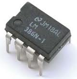
LM386 Audio Amp in a DIP package
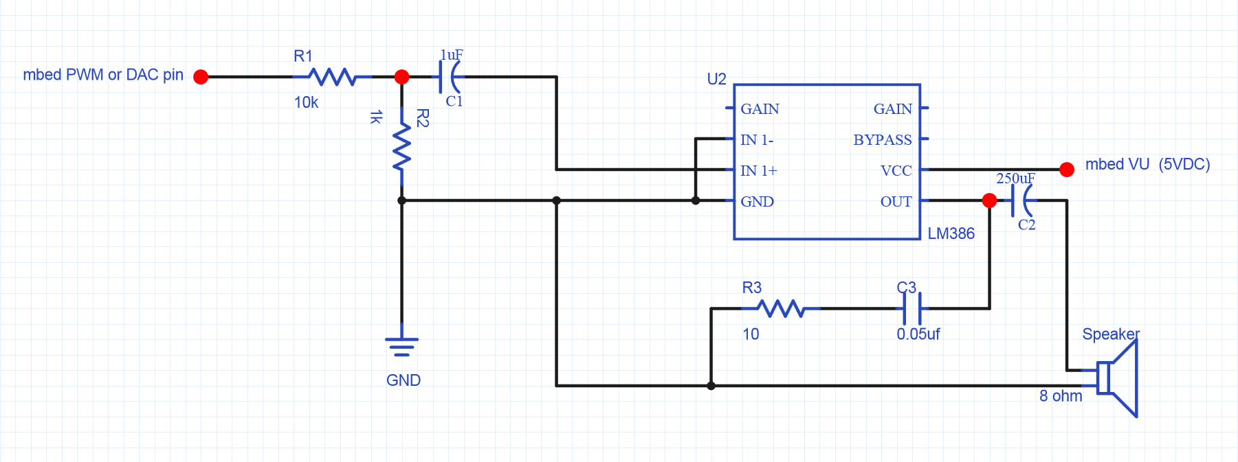
LM386 audio amplifier circuit for small 8ohm .5W speaker. A smaller value for R1 can be used to increase the volume.
Class D high-efficiency audio amp
Sparkfun also sells a breakout board with a new TI TPA2005D1 class D audio amp chip (250Khz PWM). There is an mbed demo example for this board with additional details. Class D is probably the best option for new designs, but a breakout board is needed since they are typically small surface mount ICs. It is more power efficient and does not need as many large external capacitors like the earlier linear LM386 audio amp example.
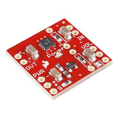
Sparkfun Class D audio amp breakout board
Wiring
| mbed | TPA2005D1 | Speaker | |
|---|---|---|---|
| gnd | pwr - (gnd), in - | ||
| Vout (3.3V) or 5V | pwr + | ||
| p26 (any PWM or D/A) | in + | ||
| out + | + | ||
| out - | - | ||
| Any DigitalOut px(optional) | S (low for shutdown) |
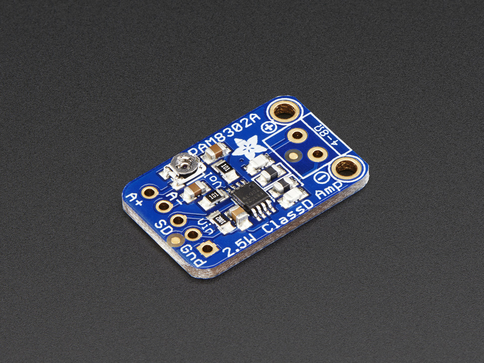
Adafruit also has a new lower cost Class D audio amp breakout. It even includes a tiny volume control pot on the board. There is an mbed demo for this board with additional details.
I2S Digital Audio Class D Amps
If a Class D audio amp driver is used, designers should also consider using I2S instead of analog or PWM outputs. I2S is a digital audio standard for input or output. Both stereo and mono modes are supported at different frequencies. Many new Class D audio amps have I2S digital audio inputs. The audio sample values are shifted out using a digital I/O pin and two clocks. LRCLK is the left/right channel select for stereo, and BCLK is the bit clock for serial data, DIN. Digital outputs provide greater noise immunity and most chips also have digital low-pass anti-aliasing filters, so higher quality audio is possible. Many processor chips such as the mbed LPC1768 have an I2S hardware controller. I2S is not one of the standard mbed APIs yet, but there are mbed I2S libraries available.
Here is a Cylon “By your Command” voice demo program using the LPC1768 and the Adafruit M98357A breakout board. The M98357A Class D Amp seen below has I2S inputs.
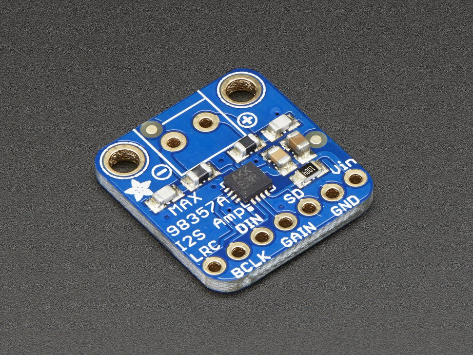
Import programflash_audio_playerI2S
Plays audio samples from an array stored in flash using I2S. Values are from an audio *.wav file that was automatically converted to a C array data source file.
In this demo, the audio sample values are stored in a large array stored in on-chip flash memory. Details on using flash to play audio are provided in a later section on this wiki page. Changing to the correct three I2S pins for other mbed boards will require consulting the hardware reference manuals for the processor chip, since I2S pins are not shown in the standard mbed pin function color figures and I2S register names might change a bit. An external 5VDC supply will likely be needed for the audio amp IC, since it can draw significant current driving speakers.
Adafruit also has another low-cost breakout board (for Pis) seen below that has I2S with stereo outputs and two small speakers. With a Pi cobbler adapter or by soldering on five jumper wires (three I2S pins and power), it can be used in a breadboard with mbed for audio projects. The tutorial at Adafruit shows the 5V power and gnd pin and I2S pin connections needed.
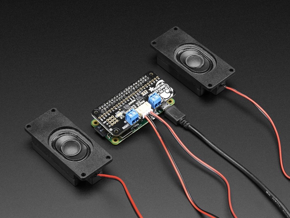
I2S demo using Adafruit Stereo Bonnet
Using PC speakers with mbed
For even more volume, a larger speaker and more powerfull audio amplifier would likely require an external power supply, since USB cable power is limited to 500MA (minus the mbed power needed). An easier option is to upgrade both the amplifier and speakers by using an old set of amplified PC speakers. Sparkfun sells a breakout board with a PC audio jack so that you can just plug them in. Adafruit has a low-cost audio jack that will plug directly into a breadboard.
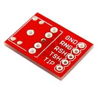
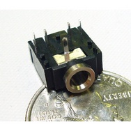
Sparkfun 3.5mm Audio Jack Breakout Board
| Audio Jack Pin | Function |
|---|---|
| GND | audio ground |
| RNG & TIP | L & R audio in |
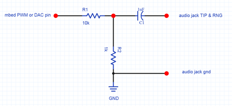
A driver circuit is not needed for amplified PC speakers hooked up to mbed using the audio jack breakout, but a voltage divider is needed to drop down the voltage to typical analog audio voltage levels. A voltage divider using a 10K resistor hooked up to the mbed output pin in series with a 1K resistor to ground drops the voltage level across the 1K resistor to a reasonable level for most PC speakers (perhaps even a bit more of a drop might be needed to avoid changing the volume level on the speakers). Passing the audio signal through a 1uf capacitor in series to block DC is also a good idea since the mbed outputs have a DC level (i.e., always >0). If the exact RC parts values are not available, anything close will work. The mbed audio signal output is mono, so just connect the left and right stereo channel inputs (RNG and TIP) together. With PWM audio outputs, it would be possible to use two outputs with one for each channel. The audio jack breakout board can also be used to connect stereo headphones, but headphones will need a driver circuit similar to the speaker setup.
A WavePlayer
The next approach for generating complex audio signals and music is to play back recorded audio using audio samples. The memory required is too large for mbed's internal memory and the audio sample values are needed so fast that an SD card is typically used to store the audio data in a file. The most common file for audio data on the PC is a *.wav file. There are several waveplayer examples in the cookbook. There are also some recorders and players. They read audio data from a *.wav file and output data using timer interrupts and the analog out pin similar to the analog example described earlier. Audacity can be used to record, edit, and convert sound file formats. Another on-line tool is available to convert audio files, online-convert and it is easier to use, but it is harder to edit the length of the audio file or adjust levels like Audacity.
The Billy Bass hack uses the mbed waveplayer code to talk
Speaker Waveplayer demo
The video above shows a very basic wave player demo using the low–cost speaker and transistor driver circuit described earlier along with an SD card for *.wav file storage. An MP3 encoded audio clip was downloaded off of a web site. Audacity was used to read in the audio MP3 clip, convert it from stereo to mono, resample it to a 16Khz sample rate and export it as a 16-bit wave file. The *.wav file size is around 2MB for 1 minute of audio. The “sample.wav” file was transferred to the micro SD card using a PC with a card reader. Some existing wave files may not play and will need to be converted using Audacity. Typically the problem is too high of a sample rate and they can be resampled at a lower rate in Audacity and it will also convert *.mp3 sound files to *.wav files. Error messages are displayed with printfs to a PC terminal application window by the waveplayer code. Most errors result in no sound.
Warning
There are several versions of the SDfilesystem library at the mbed site. Some of them have the SPI clock set a bit too low (around 1Mhz) for audio playback of *.wav files. Most new SD cards will support a 10-25Mhz SPI clock while reading data. Some new fast SD cards may run up to 50Mhz, but keep any jumper wires as short as possible. The audio will sound a bit choppy at 1Mhz. Some projects can get updated to new versions automatically and the new official version is now a bit conservative with only a 1Mhz clock. So if that is an issue, try increasing the SPI data transfer clock rate a bit in the SD driver code for higher audio sample rates (found in SDFileSystem.cpp with a ".frequency(...)" used to set the SPI clock, a slower SPI clock is sometimes used for init and then increased later for faster data transfers). Another option would be to read the *.wav file from a USB flash drive. There can also be errors when using different versions of the FATfilesystem, mbed library, RTOS, and SDfilesystem libraries, so be careful when updating.
The speaker driver circuit is connected to p18 (DAC output). The micro SD card breakout was connected to mbed using the standard cookbook micro SD file system wiring for the Sparkfun breakout board. The micro SD card is inserted in the breakout board and the demo program is started. The wave player software opens the SD card sample.wav file, reads the data, and outputs the sample values to the D/A.
The audio in the clip was recorded directly from the speaker using only the basic 2N3904 driver circuit. Using the LM386 audio amplifier or a Class D amp circuit from the earlier sections, the volume increases and there is a bit less distortion. The audio quality and volume improves significantly if a set of PC speakers is used instead along with the simple 10K:1K voltage divider circuit described earlier for the audio jack breakout board. A complete project with the waveplayer and SD filesystem libraries, and main demo program is available in the import link below. A "sample.wav" file will also need to be copied to the SD card.
Import programWavePlayer_HelloWorld
A basic wave player demo using the cookbook waveplayer and SD file system examples with a low-cost speaker and transistor
Another wave player example is seen in the video clip below. In this example, the LM386 audio amplifier circuit described earlier is used. Multiple *.wav files are played from the SD card using the waveplayer and at the same time the Ticker and BusOut APIs are used to periodically interrupt and run a function with the code to shift the LEDs. A more evolved Cylon needs a few more LEDs, perhaps a chain of Shiftbrites.
The waveplayer does not return until it finishes playing the wave file, but it can be setup as a thread using the mbed RTOS. This enables other code to be run in other thread(s) while playing *.wav files. An example can be found in LED lighting and sound effects for modelers and miniaturists.
Here is another example using the waverplayer with the RTOS and an SD card. As of 4/18/17, I had to use older versions for the SD, file system, mbed, and RTOS libraries to get it to work without an SD fopen error (so update any libraries at your own risk!).
Import programWavePlayer_HelloWorld_RTOS
waverplayer RTOS demo - at present time older libraries were needed to avoid SD open errors - so don't update them
The waveplayer code can be modified to use a hardware PWM output bit. An example using the mbed application board with a set of PC speakers is shown in the video below. It uses a USB flash drive to store sound files.
Waveplayer demo on mbed using PWM and PC speakers
WavePlayer for mbed OS version 5
The wave player code for OS 2 does not currently work in the new mbed ver 5 RTOS. The newer audio player example for ver 5 could likely be used instead, but is also has an OS mutex runtime error currently on the LPC1768 (9/19). It is available at https://github.com/ARMmbed/mbed-os-audioplayer with a demo at https://os.mbed.com/docs/mbed-os/v5.13/tutorials/usb-wav-audio-player.html. An updated version of wave_player for OS 5.0 for the mbed LPC1768 that does run can be found at : https://os.mbed.com/users/HighTide/code/wave_player/ and a demonstration program can be found here: https://os.mbed.com/users/HighTide/code/waveplayer_v5_demo/. This version writes to both a PWM output pin and directly to the DAC's registers (uses mbed LPC1768 I/O register names - change for other boards) to avoid the current OS 5 mutex problem. Select the output needed (DAC or PWM) for your application and the other one can be deleted. Increasing the PWM clock rate to play audio from the default 50Hz can break some other PWM code such as (RC ) servos, if it is setup for the default 50Hz clock since all of the PWM outputs typically have only one clock. The SD file system drivers are added by a line in the project's mbed_app.json file now in version 5. It might also be a good idea to increase the SPI clock rate to read the SD card faster for audio playback using "sd.frequency(25000000);" after sd.init and that should enable higher audio sample playback rates. Some new fast SD cards (Class 10?) may run up to 50Mhz, but keep any jumper wires as short as possible.
Using Flash to play Audio Clips
Short audio clips can be stored in on-chip flash memory instead of using a SD card or USB drive file. There are tools available to convert audio wav files to C source code that initializes a large array with the sample values from the wav file. Keep in mind that audio samples will use a lot of flash memory (as much as 8-80K bytes/second) so this is not an option to store several long song files. It does work for applications that only need a few seconds of audio. An example program using this approach for mbed is available below:
#include "mbed.h"
AnalogOut speaker(p18);
Ticker sampletick;
DigitalOut myled(LED1);

//setup const array in flash with audio values
//from free wav file conversion tool at
//http://ccgi.cjseymour.plus.com/wavtocode/wavtocode.htm
//see https://os.mbed.com/users/4180_1/notebook/using-flash-to-play-audio-clips/
#include "cylonbyc.h"

#define sample_freq 11025.0
//get and set the frequency from wav conversion tool GUI
int i=0;

//interrupt routine to play next audio sample from array in flash
void audio_sample ()
{
    speaker.write_u16(sound_data[i]);
    i++;
    if (i>= NUM_ELEMENTS) {
        i = 0;
        sampletick.detach();
        myled = 0;
    }
}
int main()
{
    while(1) {
        myled = 1;
//use a ticker to play and send next audio sample value to D/A
        sampletick.attach(&audio_sample, 1.0 / sample_freq);
//can do other things while audio plays with timer interrupts
        wait(10.0);
    }
}
Import programflash_audio_player
Plays audio samples from an array stored in flash. Values are from an audio *.wav file that was automatically converted to a C array data source file.
Complete step by step instructions are on the Using Flash to play Audio Clips wiki page.
Using DMA to output Audio
There is not an official mbed API for DMA (Direct Memory Access) controllers, but there is a DMA library available for the mbed LPC7168 platform. This LPC1768 program uses the MODDMA library to setup a DMA controller to transfer a memory buffer containing 360 precomputed points on a 1 Khz sine wave to the DAC.
Import programmbed_DMA_DAC_sine_demo
MODDMA demo program for LPC1768. Uses DMA to output a 1Khz sine wave to the DAC (p18). Main just blinks LED1.
Examine the demo program found in the file example4.h. Timer1 controls the DMA data rate to produce a 1 KHz sine wave output on the DAC (p18) with 360 samples per cycle (360KHz). After main computes one cycle of sine wave values to initialize the buffer and puts them in the format needed for the 32-bit DAC output register (i.e., it also includes a DAC speed/power bit and many bits are zero), it starts the DMA transfer by providing the src and dest addresses along with number of values to transfer, and programs the Timer used by the DMA controller with the 360 KHz audio output sample rate.
The DMA uses double buffering ping/pong style. This is a common setup and while one buffer is doing a DMA transfer the other buffer can be loaded with new data or processed by other code. Main just blinks LED1 in a loop while the DMA controller does all the work outputting thousands of sine wave values to the DAC on p18. The other two LEDs show which buffer is being used for DMA. These are changed in the TC0,1 DMA interrupt functions that are called when a DMA buffer transfer is complete. For the demo, monitor p18 using a speaker or oscilloscope to verify the 1 KHz sine wave output, along with the blinking LED1. While DMA supports higher output rates, getting recorded audio data streaming from a mass storage device this fast is still an issue.
Media Player using a smart LCD
The mPod media player seen in the video below uses the waveplayer for audio output and the smart color LCD to play video from its SD card.
MP3 audio player hardware
There are also some software only MP3 player code examples in the cookbook, but memory for the RAM buffers is a bit limited. There may not be enough RAM left to also support networking and/or the RTOS in an application, if mbed is doing software only MP3 decoding. Also the DA on some processors might not have enough bits or support higher audio sample rates.
The final approach is to add an advanced audio IC with an internal microcontroler with firmware such as an MP3/WAV player chip. Recently, some very low cost MP3 player modules have been introduced. They have been used in Arduino projects so they are widely available from several sources and have even been cloned with a few different parts on the module.
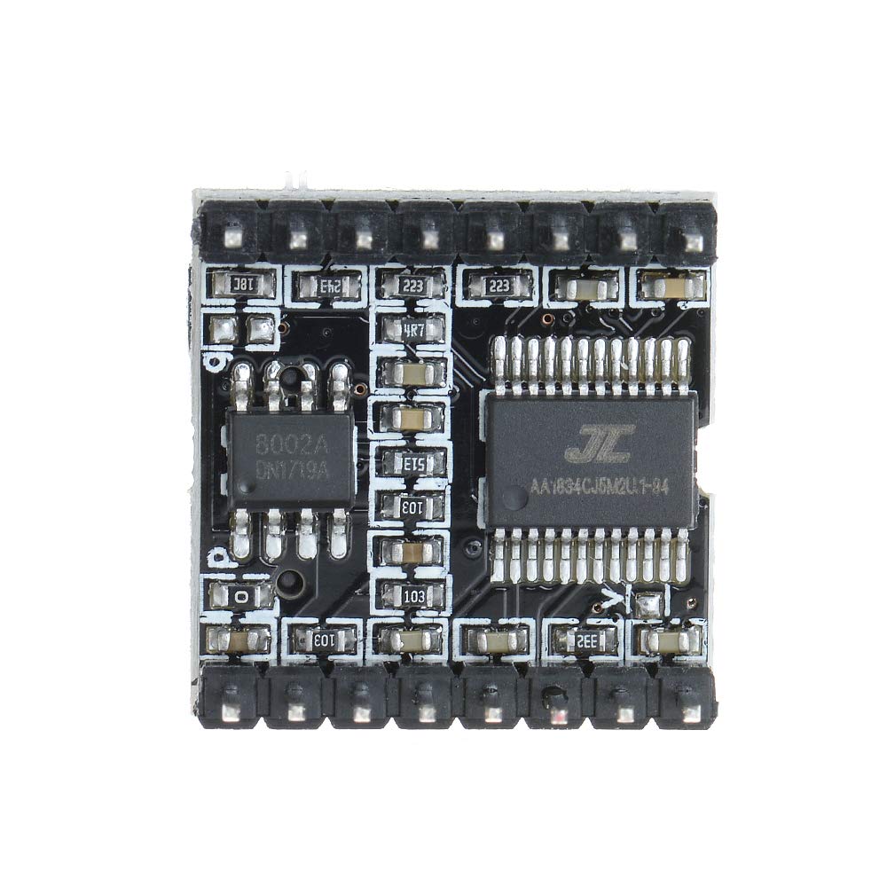
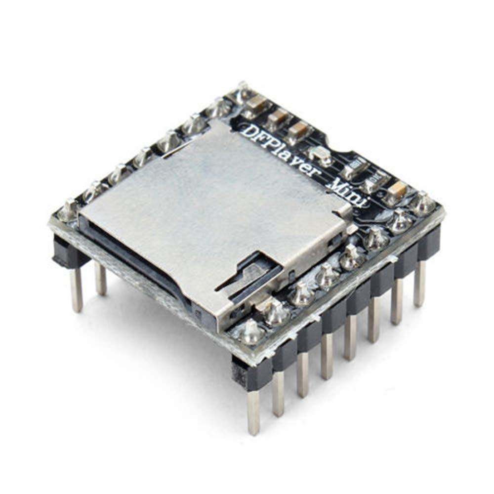
The DFPlayer mini modules are available for under $3 from some places like Amazon or Alibaba. It plays the common sound file formats including MP3 at up to 44Khz with a 24bit DAC and even contains a 3W driver for a speaker with stereo outputs for headphones. They have a uSD card slot on the board for music files or it can read a USB flash drive. Audio file names will require a three digit numeric prefix, 00x*.* . There are also a bit larger versions of the module with a headphone jack, but no audio amp. It needs a serial port for control running at 9600 baud or pushbuttons. There is an mbed driver library available at: https://os.mbed.com/users/dimavb/code/DFPlayerMini/file/a637be95c1ea/DFPlayerMini.cpp/ and there is a datasheet available and there is another more complete datasheet. As seen in the image above, the DFPlayer module contains a small audio amp IC (left) and an YX5200-24SS MP3 chip(right).
Sparkfun also makes an older breakout board with a similar device. The advantage is that the decoder and buffering needed is built into the chip along with improved D/As, and the mbed processor has more time and data memory available to do other things while audio is playing. The disadvantage is that it increases system cost.
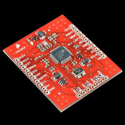
Sparkfun MP3 decoder chip breakout board
Student mbed project using MP3 breakout board
There are even some sound modules with an audio chip, audio jack, processor, and SD card slot on a small PCB.
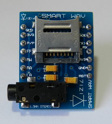
SMARTWAV intelligent embedded Audio processor unit
SMARTWAV mbed player demo
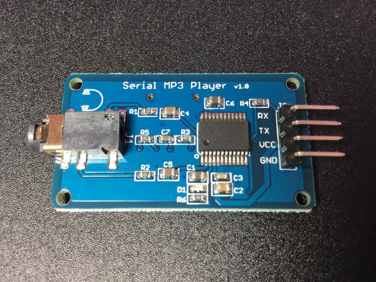
There are some new very low cost MP3 player breakout boards with an on-board uSD card slot for MP3 audio files available at https://www.resistorpark.com/arduino-compatible-mp3-player/. Commands are sent to the board over serial port.
Other Audio Project Ideas
AM/FM/SW Radio
New Sparkfun breakouts recently became available for both the MP3 player and AM/FM/SW Radio receiver ICs. These new breakouts would solve or simplify some of the issues in these older student projects.
The chip used in Furby is available on the EasyVR breakout board and it does both audio playback and speech recognition as seen in the video demo below that uses speech recognition to control the LEDs. It also prompts for user input with audio using recorded speech samples that are flashed to the board.
The Emic2 Speech synthesis module can convert text from a printf to speech.
Emic 2 hello world demo
6 comments on Using a Speaker for Audio Output:
Please log in to post comments.



I'm trying to get one speaker to play the melody of a song and another speaker to play the bass of a song. I've managed to get the melody itself to work well but when I add in another loudspeaker I encounter a couple of problems.
The first one is; when using my function to play a note I need to use a wait for the duration of the note. I don't know how to make the program do something else while it is also waiting, ie, I can't make the melody speaker play a tune over the top of a single bass note due to the program waiting for the bass note to finish.
This means I am unable to set a duration for one speaker in the function so I have to jiggle the durations around, leaving the bass on (setting the frequency to a note) then leaving it while I play the melody until I need to change the bass note or turn the bass off.
While doing this, I encountered the second problem. I believe it's do with how pwm actually works. If I have something like this:
loudspeaker1.period(1/523.25); note c
loudspeaker1 = 0.5;
wait(2);
loudspeaker1.period(1/587.33); note d
loudspeaker1=0.5;
loudspeaker2.period(1/329.63); low note e
loudspeaker2 = 0.5;
wait(2);
loudspeaker1 = 0;
loudspeaker2 = 0;
This should make loudspeaker1 a note c for 2 seconds then it should change to a note d while the loudspeaker2 goes to a low note e. This doesn't happen, instead loudspeaker1 is forced to go to a low note e at the same time loudspeaker2 goes to a low note e. They should then turn off after 2 seconds, which they do.
Any help would be much appreciated, thanks.