JTAG
Adding a JTAG connector to MBED
MBED is cool, but without ability to step through your code with a real debugger it may be very difficult to troubleshoot some programs. While thinking of the problem, it occurred to me that it is possible to add a JTAG connector to MBED. It can be done so that the existing MBED functionality is not affected while the JTAG is unplugged, and once plugged, JTAG can take over the control from the MBED's MBED chip (the little guy that provides USB connection).
The JTAG connector I chose is a standard ARM 20-pin 0.100" connector compatible with J-Link http://shop-us.segger.com/J_Link_EDU_p/8.08.90.htm and other emulators/debuggers.
Connector pinout and wiring is the following:
| pin | signal | connect to | (Wire color on the pictures) |
|---|---|---|---|
| 1 | Vtref | +3.3V | (GRN) |
| 3 | nTRST | IC6.4 | (YEL) |
| 5 | TDI | IC6.2 | (WHT) |
| 7 | TMS | IC6.3 | (GRN) |
| 9 | TCK | IC6.5 | (BLU) |
| 11 | RTCK | IC6.100 | (YEL) |
| 13 | TDO | IC6.1 | (BLU) |
| 15 | nSRST | IC6.17 | (WHT) + 10k Ohm resistor to +3.3V |
| 17 | DBRQ | (NC) | |
| 19 | DBGACK/ V5-supply | (NC) | |
| 2 | Vcc | (NC) | |
| 4 | GND | GND | (BLU) |
| 6 | GND | GND | |
| 8 | GND | GND | |
| 10 | GND | GND | |
| 12 | GND | GND | |
| 14 | GND | GND | |
| 16 | GND | GND | |
| 18 | GND | GND | |
| 20 | GND | IC1.57/R9/C5 (IF_N_RST) | (YEL) |
IC1 is the MBED chip
IC6 is LPC1768 chip
+3.3V and GND is convenient to pick up on a bypass cap next to IC6 on top side
All magic of the connector operation happens by wiring connector's pin 20 to MBED chip's reset. Once JTAG is plugged in, MBED chip is kept in reset by shorting pin 57 to ground.
One modification is required - remove R2 (10k) on the backside.
YOU WILL NEED A MICROSCOPE! and very thin wires and steady hands besides a sharp tip solder iron, fine tweezers and some solder & flux.
I chose to solder an SMT connector to a piece of breadboard and glue the breadboard (Loctite) to the top of the LPC1768 chip (after soldering +3.3V & GND wires to the bypass cap). Then solder wires to connector pins, and carefully solder other ends to the pins of IC6/LPC1768 (that's where you need a microscope and fine tweezers). Note that there is a pullup resistor on nSRST which replaces removed pulldown R2 resistor. I placed a 0402 SMT resistor on connector pin and then bridged +3.3V wire across it on the way to the other pin.
Other thoughts
The 20-pin 0.100" connector is quite large and protrudes from MBED board. It is possible to cut off sides of black plastic so it is flush with the board. It is also possible to adapt one of smaller connectors, but for me it requires an adapter, so it is less convenient.
Pictures
| Top view: | 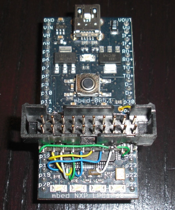 |
| Top view / angle to JTAG signal wires: | 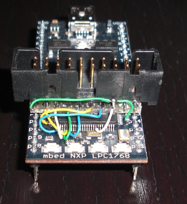 |
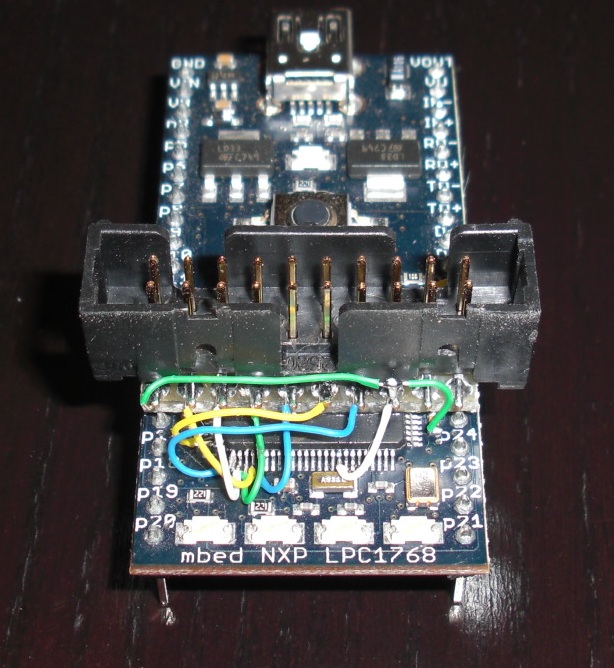 | |
| Top view / angle to GND pins: | 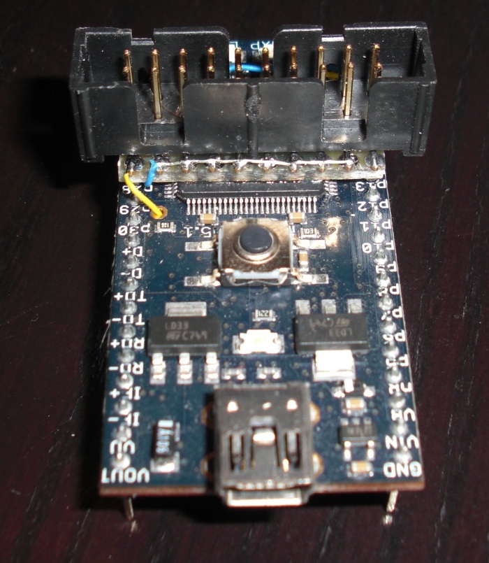 |
| Bottom view / angle to IF_N_RST wire: | 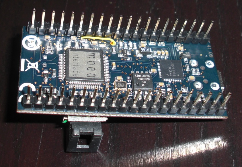 |
| Bottom view / angle to the removed resistor R2 (note it is simply moved to one of two pads - saved for later): | 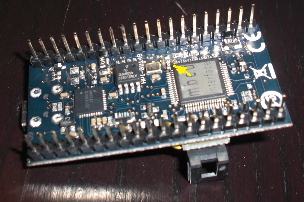 |
6 comments on JTAG:
Please log in to post comments.

This is super. Last year, I went half way through this and then got stuck with disconnecting the MBED magic chip. The idea of putting it in reset is brilliant !
Thanks for posting. I'm going to try this tomorrow.
Zainul.