Starburst LED display
LCD displays are widely used. However, we still see lots of LED based displays. They are relatively cheap, even for larger displays, and look good since they have nice bright colors. The best known type is the seven segment display. They can display numbers 0-9 and some characters like A-F. The seven segments are usually identified by the characters a-g. Each segment consists of one or more LEDs. Each segment has a separate external pin and they all share a common anode (or common cathode) pin. In some cases the display also features an additional LED for the decimal point (dp).
Displays with more than one digit in a single package are also available. The corresponding segments of all digits are all connected and brought out on a single pin. The common cathodes (or anodes) are available separately for each digit. This approach reduces the number of pins. A processor will activate each digit sequentially at a high update rate (> 75 Hz) and the result is that all digits seem to be on continuously. This solution is known as multiplexing and it serves to reduce to number of required processor pins for driving the display and also reduces the required electrical power.
Another type of LED display is more suitable when you need more flexibility to display characters or symbols. These types are known as 14 or 16 segment 'starburst' LED displays.

The individual segments are identified a-n as shown in the picture above.
I salvaged a 4 digits 14 segment display from a sat-receiver and developed some software for mbed to drive it. However, even when we multiplex the segments, we still need some 14+4 pins to connect it to mbed. That is a waste of pins. A better solution is to use mbeds high speed and add some circuitry that converts a serial bitstream from mbed in the required 18 parallel controlsignals. The salvaged display unit did exactly that. It used three 8-bit serial-in parallel-out shiftregisters of type 74595. The diagram below shows the reverse engineered schematic after some modifications that I did on the circuitboard.

Higher resolution picture is here: /media/uploads/wim/starburst_if.jpg
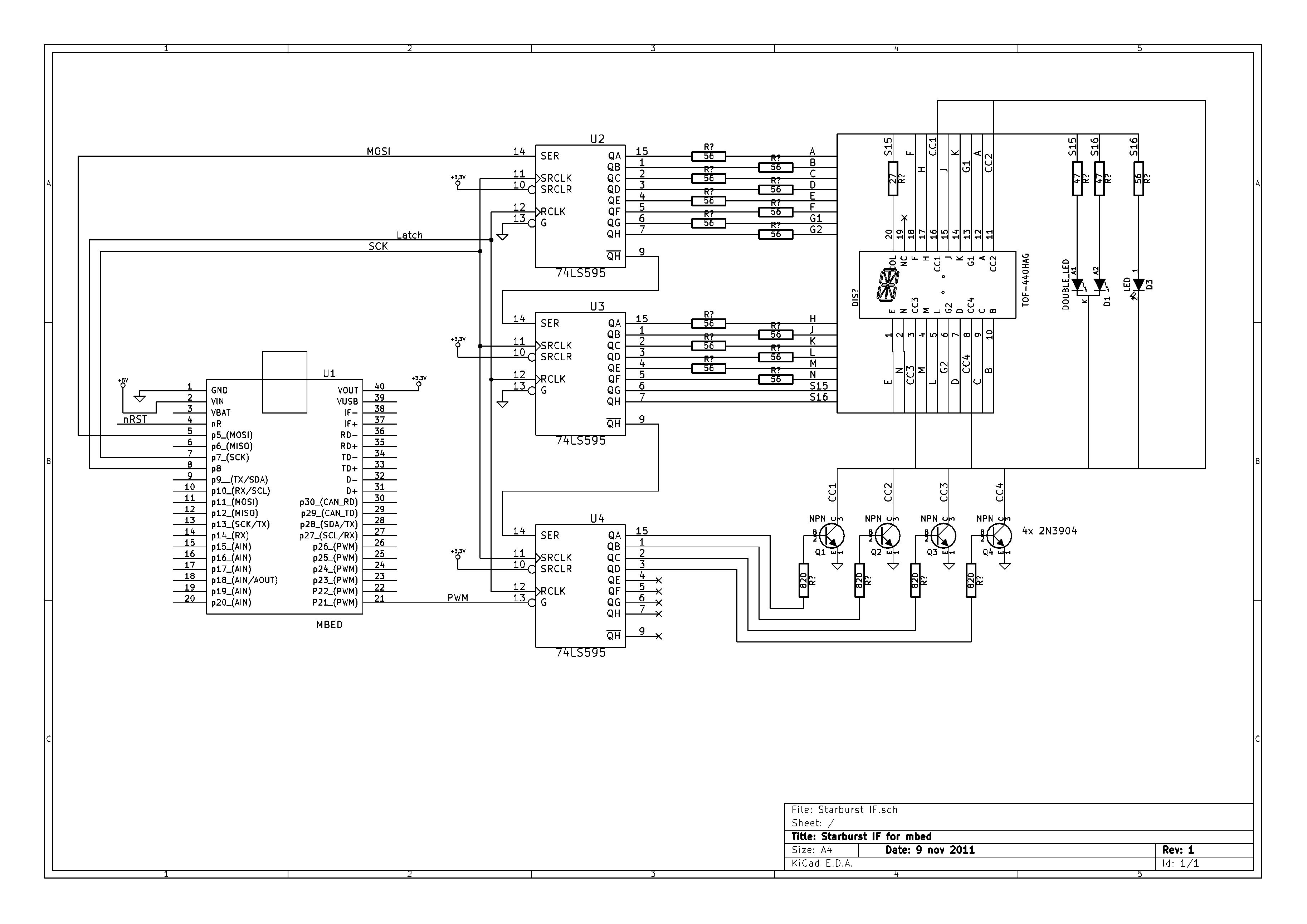
Ok, so how do we send data to the shiftregisters. Easy, use the spi port. The 14 segments are stored in the first two shiftregisters, the common cathodes are activated by the third shiftregister (only 4 pins are used). The common cathodes need more current and a separate npn transistor takes care of that. The segments can be driven directly from the 74595 outputs using a series resistor. We have 2 spare pins on the segment registers and these are used to drive the colon LEDs on the display, an additional LED and a bi-color LED.
The starburst class software has all the internal multiplexing code and Tickers to drive the display at the required update rate. You can simply use printf to send data to the display. Additional features are a blinking display (2 Hz), LED and Bicolor LED control and even a standalone scrolling text that requires a single printf to load a string for displaying. A simple example:
#include "mbed.h"
#include "starburst.h"

#define MOSI p5
#define MISO p6
#define SCK  p7
#define CE   p8
#define nOE  p21

SPI spi(MOSI, MISO, SCK);           // mosi, miso, sclk
Starburst starburst(spi, CE, nOE);  // Multiplexed Starburst Display, SPI controlled

int main() {

    starburst.locate(0);
    starburst.printf("BILL");

    starburst.set_blink_mode(true);
    wait(5);
    starburst.set_blink_mode(false);


//    starburst.scroll_printf ("Hello World. The answer is %d ", 123456);
    starburst.scroll_printf ("Hello World ");
    starburst.set_scroll_mode(true);

    starburst.set_led(true);

    starburst.set_bi_led(BI_RED);
}
This is what my prototype looks like:

The code can be found here: http://mbed.org/users/wim/programs/mbed_starburst/m0gd9j
There is room for further improvements. The nOE pin is connected to one of mbeds PWM outputs. This may be used to control the display brightness. It would also be useful to support individual blinking digits in case you want to edit characters shown in the display by using a few buttons. Obviously, you can modify the table that defines the 14 segment characters to add your own symbols. The current version supports ASCII character codes between 32 and 127. You can also add more LEDs or an additional 4 digit display. That needs 4 more common cathode transistors connected to the unused shiftregister outputs.
Have fun!
Please log in to post comments.
Starburst LED display
Driver for a 4 digit 14 segment Starburst LED display using SPI
Page owner:  Wim Huiskamp
Created 10 Nov 2011.
Last updated 09 Sep 2013