mbed (LED blink) code on LPCXpresso-LPC1768 (-LPC1769)
| このページは日本語でも記載されています.日本語版はこのページ後半をご覧ください. | This page is written in Japanese as well. Please find it in 2nd half of this page. |
As Chris in mbed team mentioned here (http://mbed.org/users/chris/notebook/prototype-to-hardware/), the mbed code runs the LPC1768 bare metal.
To confirm this, we can try it in several ways. Do it like that web page explaining or LPC1768 boards from many vendors.
And now we have another option: LPCXpresso-LPC1768.

I've just tried to run a program LED blinking. Please find the summary below.
Code modification:
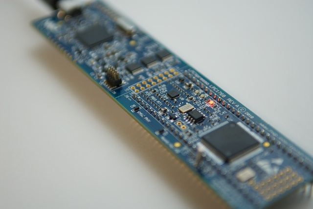
The LPCXpresso board has an LED which directly (through a resister) connected to the LPC1768 port but the hardware configuration is different from the mbed.
Now I'm going to use the mbed's simple LED blinking sample (the code which is provided when the new program generated) but it requires a modification, because I cannot use "LED1".
The LED on the LPCXpresso is tied to "P0[22]". It can be found in the schematic (http://ics.nxp.com/support/documents/microcontrollers/pdf/lpcxpresso.lpc1769.schematic.pdf), page 5.
So the initializer of "myled" should be changed from "LED1" to "P0_22".
#include "mbed.h"

//DigitalOut myled(LED1);  //  original
DigitalOut myled(P0_22);   //  modified

int main() {
    while(1) {
        myled = 1;
        wait(0.2);
        myled = 0;
        wait(0.2);
    }
}
After the compile, the binary file need to be stored somewhere.
Programing internal flash memory of the LPC1768:
To run the binary file (downloaded from compiler page) contents should be cpoied on the LPC1768 internal flash memory.
The LPCXpresso IDE can help this. Launch the IDE and find a button of chip icon.
![]()
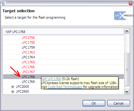
After pressing this button, it will pop-up a dialog box to select a target chip type ... choose LPC1768.

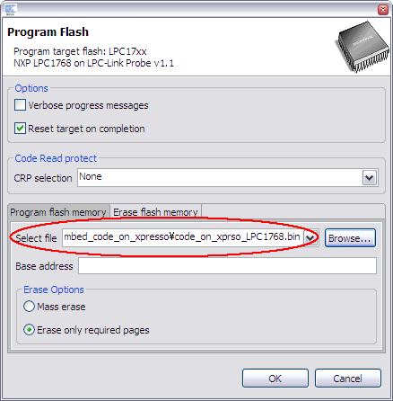
Then the LPC-Link software will be launched automatically and it will ask which file should be programmed. The field of the base address may be OK to leave it blank. The "0" will be used if it is not available.

Choose the file you just stored. After the program completion, reset the LPCXpresso by US disconnect and connect.
You will find the LED (LED2) is blinking on the LPCXpresso.

mbedでコンパイルしたコードをLPCXpresso-LPC1768で使う
mbedチームのクリスさんがこのページ(http://mbed.org/users/chris/notebook/prototype-to-hardware/)で解説しているようにmbedの実行コードはLPC1768チップ単体の上で動作します.
この検証はそのwebページで開設されている方法や,数多くのベンダから提供されているLPC1768基板を使って行うことができました.
これに加えて先日もうひとつの選択肢が増えました.LPCXpresso-LPC1768です.
早速LED点滅プログラムを動作させてみました.以下にそのまとめを書いておきます.
コードの変更:
LPCXpresso基板上にはLPC1768のポートに(抵抗を介して)直接接続されたLEDが1個あります.しかしmbedとはハードウェアの構成が違います.
ここではmbedの簡単なLED点滅サンプル(Newプログラム作成時に用意されるコード)を使おうとしているのですが,「LED1」がないため変更が必要になります.
LPCXpressoのLEDは「P0_22」に接続されています.これは回路図(http://ics.nxp.com/support/documents/microcontrollers/pdf/lpcxpresso.lpc1769.schematic.pdf)の5ページで確認できます.
というわけで,myledの初期化子を「LED1」から「P0_22」に変えておかなければなりません.
#include "mbed.h"

//DigitalOut myled(LED1);  //  original
DigitalOut myled(P0_22);   //  modified

int main() {
    while(1) {
        myled = 1;
        wait(0.2);
        myled = 0;
        wait(0.2);
    }
}
コンパイルしてできたバイナリ・ファイルは,どこかに保存しておきます.
LPC1768内蔵フラッシュへの書き込み:
(コンパイラページからダウンロードした)バイナリファイルを実行するには,その中身をLPC1768の内部フラッシュにコピーしなくてはなりません.
これはLPCXpresso-IDEを使って行うことができます.IDEを起動しウィンドウ上部に並ぶチップの絵のアイコン・ボタンを使います.
![]()
ボタンを押すとチップ・タイプ選択のダイアログ・ボックスが現れます ... LPC1768を選択します.

その後,自動的にLPC-Linkソフトウェアが立ち上がり,どのファイルを書き込むのかを聞いてきます.ベースアドレスの入力欄はそのままの空白で構わないようです.何も入れないと0が適用されます.

先ほど保存しておいたファイルを指定してください.書き込み終了後USBコネクタの抜き差ししてLPCXpressoをリセットすると,LED(LED2)の点滅が確認できます.

8 comments
You need to log in to post a comment


I tried this and it works!
I bought some LPCXpresso's because they are much cheaper than the mbed.
Unfortunately the IDE is horrible and after hours I could not get it to work the way I like to program.
Thanks!