Turning an mbed circuit into a custom PCB
OK, so I have a nice little circuit that I have plonked my mbed into and it all works fine. So what next?
I have reached this point with my final year university project and want to finish it of and migrate the mbed core components (namely the LPC1768 micro) onto my own board. I figured that it was best to start documentin this from the beginning as if I leave it all to the end I will almost certainly forget something important!
So the first port of call is to figure put what I really need to take from the mbed. Using Chris Styles' notebook page prototype-to-hardware for reference I work out that there is quite a lot I can get rid of namely Ethernet, JTAG, and the USB stuff (because I will use an FTDI32RL chip for the comms instead).
As I don't have the full version of Eagle I will use the free version. This limits me to a board smaller than 80 x 100 mm and only 2 layers. Also using this free version only 1 schematic sheet can be used, so I have to redraw Chris' work on a single sheet. Along with the required mbed components I also add in my circuit components to form a super circuit!
I planned to put a link to this file here but can't figure out how to add the file to this page :(
Instead here is a screen grab...
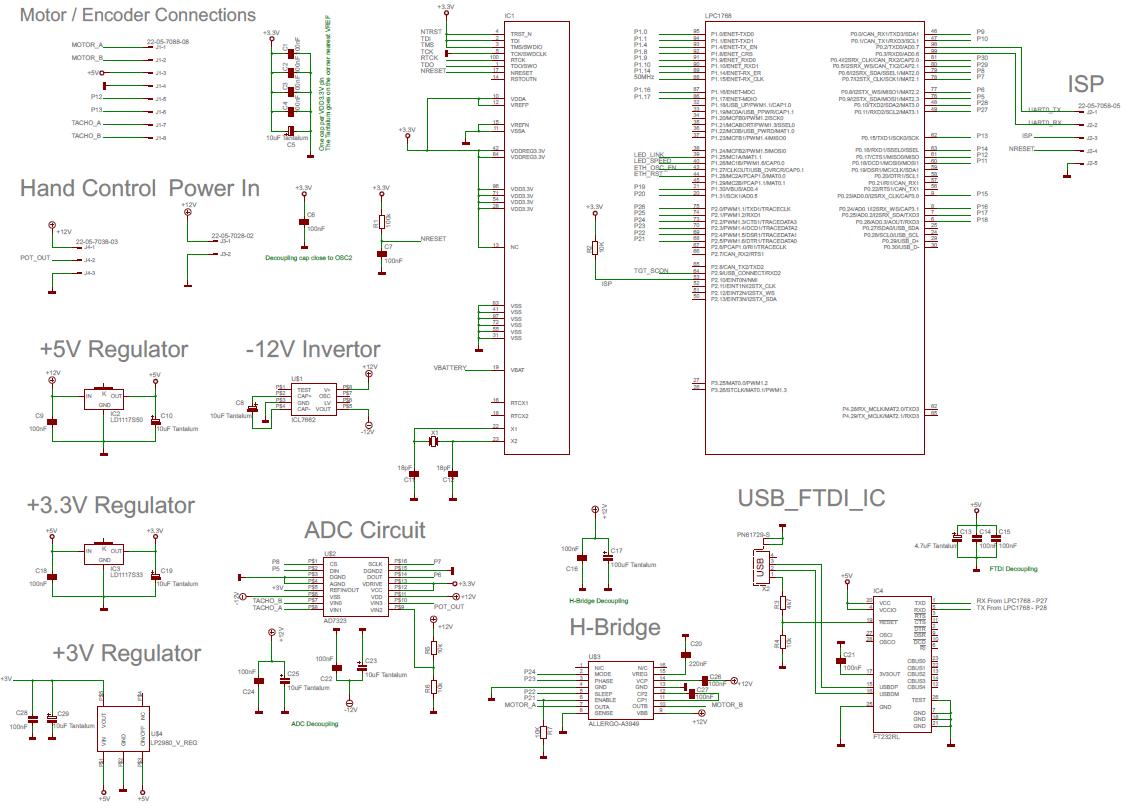
From this schematic I start to layout the board. Because nothing on the board is high frequency I'm not too constrained as to where thing need to go. I aslo add on a 5-pin Molex header to allow programming of the chip. This header consists to GND, UART0 TX & RX (LPC1768 pins 98 & 99), ISP (pin 53) and NRESET (pin 17). So a few hours later the board is laid out and I get...
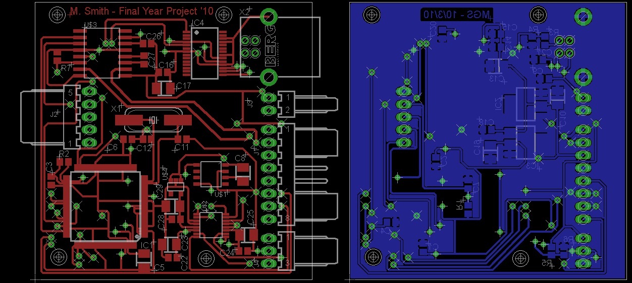
So on the left is the view from the component side (top copper, holes, vias, pads, silkscreen) and the solder side on the right - nicely flood filled with a ground plane.
So I'm planning to get some nice PCBs spun via PCBTrain or someone. They will want some CAD files to manufacture the PCB. I found this webpage detailing how to use Eagle to get the required files. After I have read through it and followed the instructions I end up with 10 or so files that I can send away to get a board spun.
I decide to get the PCB made at PCBTrain, send of the required files and wait for the boards to come in...
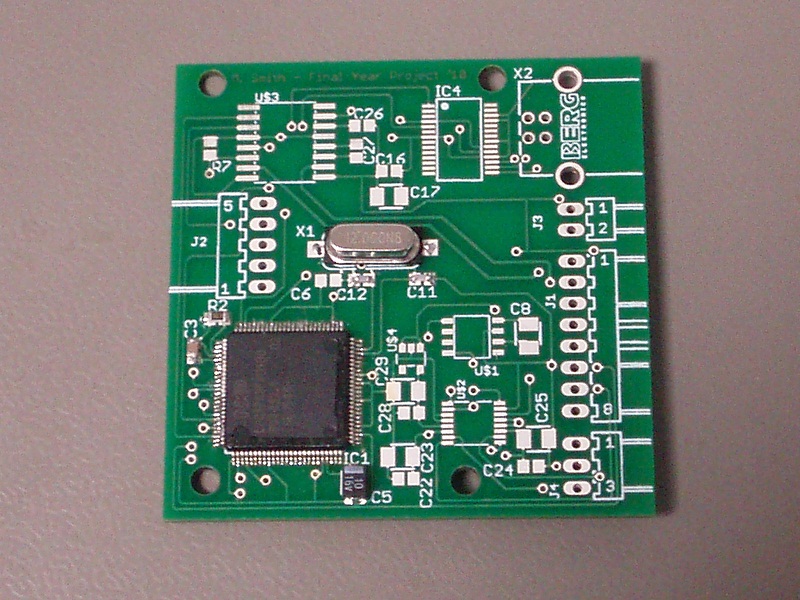
And 5 days later they do...
So the first thing to do is out down the minimum components to get the LPC1768 running. So I solder down the LPC1768 IC and it's decoupling caps, the +5 & +3.3V regulators, the crystal and it's 18pF caps, the 100nF cap and 10k resistor for the reset line, the 100k pull up for the ISP.
At this point the board looks like this...
I also decide to solder on a 5 way header for the ISP interface to make life a little easier. The next thing to do is download a few programs namely Flash Magic and bin2hex (or if your running a 64-bit system use this bin2hex instead
With these 2 downloaded and installed the first test is to communicate with the LPC1768 on the PCB. To do this go to Chris Styles' notebook page prototype-to-hardware and copy the code from the 'Communicating with the LPC1768' section, create a new program in the mbed complier and paste the code into main.cpp.
Complie the code and download it to the mbed. The wire up the mbed to Chris' instructions, namely...
mbed         LPC1768
============================

p30(isp)     P2.10  (pin 53)
p29(reset)   nReset (pin 17)
p28(TX)      RXD0   (pin 99)
p27(RX)      TXD0   (pin 98)
Now install the serial drivers for the mbed (if you havn't done this already) and fire up teraterm or hyperterminal (make sure the terminal program is set to 19200 baud rate). Power up the LPC1768 PCB, connect the terminal program to the mbed com port and type '?'
With a bit of luck you should see...
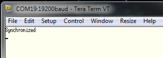
If you see this then you have comms to your custom board! A second sanity check is to fire up Flash Magic. Select device as 'LPC1768', COM Port as your mbed port (19 in my case), and Baud rate of 19200. Reset you mbed and go to the ISP tab and then 'Read Device Signiture...' you chould see something like...
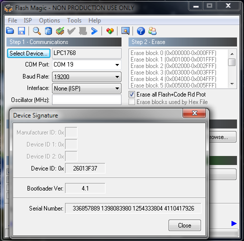
Proving you have comms (note: this will fail a read if you havn't reset the mbed!)
I guess the next thing is to load a program onto the LPC1768. To do this write the program in the mbed complier and compile the normal way, but save it to the same directory as BIN2HEX. Then open the MS-DOS command propmt.
I hate DOS, I can never remember the commands, because of this I put both the BIN2HEX program and my freshly complied file into the defalut DOS directory so I don't have to navigate around anywhere!
Finally cahnge the name of the file you want to download onto the LPC1768 to something short (<8 characters). In the command prompt window type BIN2HEX XXX.bin XXX.hex where XXX is the filename of your complied file. You should see...
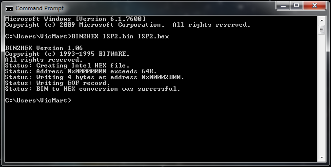
And the converted file should appear in the same directory. So you now have the hex file required to put onto the LPC1768, you just need to get it on there!
The last bit is to use Flash Magic to get the hex onto the IC. This is done by setting us Flash Magic as above and in the Step 3 box browsing to the location of your newly created hex file. Tick 'Verify after programming' in step 4 and then click start. The program should flash over (literally - watch the LEDs on the mbed!) in 30 seconds or so.
Then your program should run. I tested this with a program to flash an LED, then took a photo,
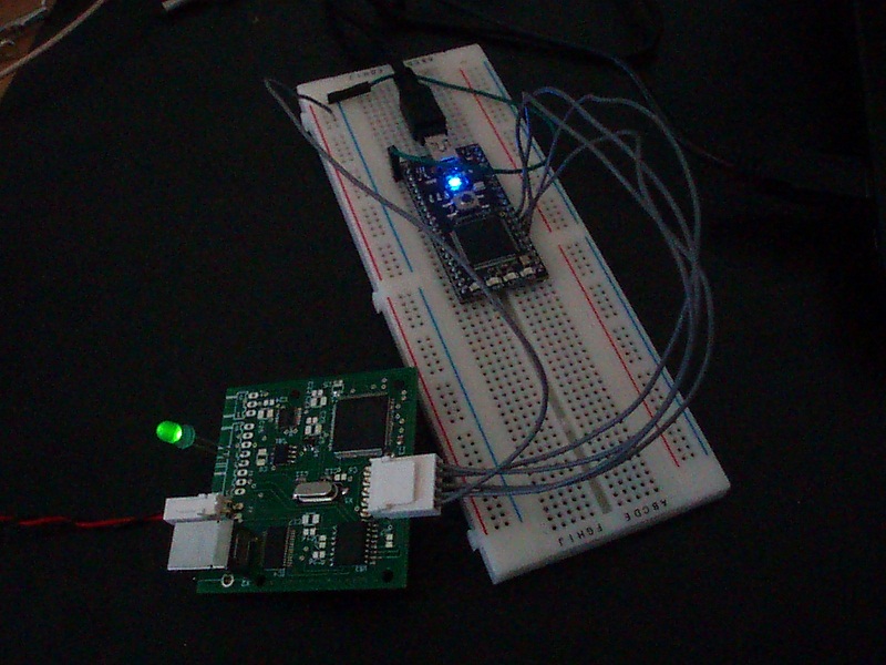
This is obviously not my finished circuit, but it shows that the LPC1768 is up and running. I now need to solder up the rest of the board and flash down the full code. I'll do that on Monday...
Fishing the PCB...
With a functioning LPC1768 the remaining work on the circuit continued. The FTDI chip for USB communication was the first to be soldered on and tested. A simple ‘Hello World’ program that printed to HyperTerminal was compiled and tested. When the PCB was then plugged into a USB port the FTDI IC installed a driver on the PC which allowed communications between the LPC1768 and PC.
The same approach was taken for the ADC and H-bridge along with their respective ancillary components. This type of methodical assembly and testing was to identify any potential problems with any of the circuit sub-systems at the earliest opportunity.
After all the subsystems had been individually tested the full program was loaded onto the LPC1768 using exactly the same process as described above.
Finally the time had come for a full system test. I was surprised that the circuit worked first time (very unusual for me!). I guess this should not be too much of a shock, it is afterall the same code and MCU that I have been developing for a while now, it just looks a bit more professional...
20 comments


You need to log in to post a comment
Turning an mbed circuit into a custom PCB
What happens when you have a nice mbed circuit and want to migrate from mbed to LCP1768 (i.e. the MCU mbed runs off)?
Page owner:  Martin Smith
Created 10 Mar 2010.
Last updated 09 Jan 2013
cool!