FlightSimInstrument
Flight Sim Instrument Project
Intro
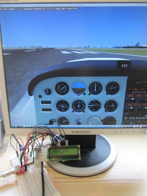
The aim of this project is to basically create an "airplane instrument" (such as an altimeter) for a flight simulator.
I used a Text LCD display since that was a bit easier than creating a dial, but if you're up for it feel free to create an analog edition! (if you do, post it in the comments :-) )
Essentially, the way this will work is that we'll extract some data (such as the air speed and the altitude) from a flight sim, and display them on a Text LCD display using the mbed. While this would theoretically be possible using the USB to Serial connection provided by the "mbed magic" chip, we'll give the new USB libraries a go! (that's more elegant and less 1969-style, too (as a figure of speech) :-) ).
Now, while some might argue, that Microsoft flight sims provide the best experience, extracting data out of those will be a pain (DLL hooks, anyone?), and beyond the scope of this project. So, we'll pick FlightGear instead, since it's open source, so worst case we can compile the necessary capabilities into the Flight Sim straight away, but as we'll see later, this won't be necessary.
From a "project management" point of view, my aim is to first get a simple prototype up and running quickly, and then expand the features until it's where I want it to be. I'll describe the process of developing the project rather than just stating "here's the end result" (if you want that now though, scroll down to the summary). I'll be updating this notebook as I go along.
This part will be written quite verbosely in a step-by-step way, apologies to the veterans who already know most of the stuff.
Disclaimer
Follow these instructions at your own risk, I've tried to be as careful as I could, but can't be held responsible if you blow something up.
Prerequisites
- mbed (I'm using the LPC11U24)
- USB connector - I used a breakout board + standard USB cable.
- Text LCD display - I'm using the following one
- FlightGear - you might as well start downloading it now; if you're on linux, check your package manager for 'flightgear', Win/Mac users should check the website for binaries.
You can of course adapt the project as you wish to suit the stuff you've got lying around. I'll be using mostly Linux for this part, but will include some notes for Windows users, too. I think things should work similarly on Mac as on Linux.
Making sure everything works
Wiring things up & testing
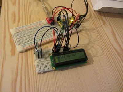
First, grab the datasheet for your LCD display (you'll usually find it on the website where you bought it from) and/or use the excellent Text-LCD cookbook page as a guide on how to wire it up.
Connecting the USB port is a bit easier, just connect the USB's D+ & D- to the mbed's D+ and D-, GND to GND and the USB VCC to mbed's Vin.
Next, I imported the USBMouse program and checked the USB wiring, as well as the Text-LCD Hello World program; the latter required me to delete the "mbed" library and import the "m0-beta" library. To do that, you click on "Import" and under "source URL" enter "http://mbed.org/projects/libraries-testing/svn/m0-beta" (this will probably change when the Cortex M0 goes into production).
Once everything's cabled up and tested, we can move on!
Sending some text from the PC to the mbed
Iteration 1: USBSerial : mbed
Aim: We'll want to send some dummy data from the PC to the mbed, and display it on the LCD screen.
Ok, using USBSerial is only slightly less hacky than using the USB-serial connection provided by the mbed magic chip (see the bottom of your board), but if you don't have an mbed magic chip this might be of interest to you.
The USBDevice library can be found here, and the following is the USBSerial class we'll be using for now:
Import library
Public Member Functions |
|
| USBSerial (uint16_t vendor_id=0x1f00, uint16_t product_id=0x2012, uint16_t product_release=0x0001) | |
|
Constructor.
|
|
| virtual int | _putc (int c) |
|
Send a character.
|
|
| virtual int | _getc () |
|
Read a character: blocking.
|
|
| uint8_t | available () |
|
Check the number of bytes available.
|
|
| bool | writeBlock (uint8_t *buf, uint16_t size) |
|
Write a block of data.
|
|
| template<typename T > | |
| void | attach (T *tptr, void(T::*mptr)(void)) |
|
Attach a member function to call when a packet is received.
|
|
| void | attach (void(*fn)(void)) |
|
Attach a callback called when a packet is received.
|
|
The USBSerial "port" on my computer ended up being the following one:
/dev/serial/by-id/usb-mbed.org_CDC_DEVICE_0123456789-if00
So we'll be using that throughout this project. On Windows, it is COM3 (after installing the driver, as explained on the USBSerial handbook page).
Now, let's create a project, and import the libraries (and of course the m0-beta library):
Import libraryTextLCD
TextLCD library for controlling various LCD panels based on the HD44780 4-bit interface
and
Import libraryUSBDevice
USBDevice stack
Next, let's write some mbed code!
Import programFlightSimInstrument-1
This project is about creating an airplane instrument (such as an altimeter) for a flight simulator running on a PC. The code will read in two space-separated \"words\" containing the altitude and airspeed, with units, from a \"USBSerial port\". See my notebook page for details.
main.cpp
#include "mbed.h"
#include "USBSerial.h"
#include "TextLCD.h"

//an LED to display activity
DigitalOut serial_activity_led(LED2);
//Virtual serial port over USB
USBSerial serial;
//The TextLCD
TextLCD lcd(p21, p22, p17, p18, p19, p20); // rs, e, d4-d7

int main() {
    //initialise the LCD
    lcd.printf("FlightSimInstru\nready!");

    //setup some buffers - could use ints, too, but this way we can let the PC decide on the units, use floats etc.
    uint8_t ias[128];
    uint8_t alt[128];
    //clear them
    memset(ias,0,sizeof(ias)*sizeof(*ias));
    memset(alt,0,sizeof(alt)*sizeof(*alt));

    //toggle an LED to show us, that the mbed is alive.
    while(1) {
        //read two space separated strings
        serial.scanf("%s %s", ias, alt);
        //write them on the LCD
        lcd.cls();
        lcd.printf("Speed: %s\nAlt: %s", ias, alt);
        //toggle activity LED
        serial_activity_led = !serial_activity_led;
    }
}
This will read two space-separated words from the USBSerial port, display them on the LCD screen next to "Speed" and "Alt", and toggle LED2 every time you send something over the USBSerial port so that you know your mbed is alive. You can test it by executing e.g. the following in your terminal:
% echo "123kt 456ft" > /dev/serial/by-id/usb-mbed.org_CDC_DEVICE_0123456789-if00
On Windows, just connect to the mbed using your favourite terminal program (e.g. Putty). See the SerialPC page for more details. You may not see any characters on the screen as you type them, depending on your settings, but if you type "123kt 456ft" (quotes for clarity) and hit enter, you should see the data on the mbed.
The results should look something like this:
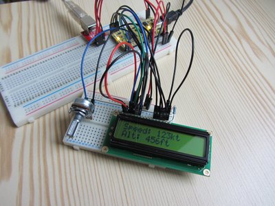
Now, all we need to do for the simple prototype, is get this data dynamically from something more exciting than a terminal!
Iteration 1: USBSerial : PC - writing data directly to the mbed
FlightGear has a quite nice feature, that allows users to define custom, generic protocols. We'll tell FlightGear to write the speed and altitude in the format that our mbed expects, and pass it the USBSerial port as "destination file" for the data. That way, it will send the data directly to the mbed.
1. Save the following file in $FG_ROOT/Protocol/speedalt.xml ($FG_ROOT is the directory that FlightGear was installed in - for me it's /usr/share/flightgear/data on Linux and C:\Program Files (x86)\FlightGear 2.4.0\data\Protocol on Windows.):
speedalt.xml
<?xml version="1.0"?>
<PropertyList>
 <generic>
   <output>
     <binary_mode>false</binary_mode>
     <var_separator> </var_separator>
     <line_separator>\n</line_separator>
     <preamble></preamble>
     <postamble></postamble>

     <chunk>
       <node>/velocities/airspeed-kt</node>
       <type>int</type>
       <format>%dkt</format>
     </chunk>

     <chunk>
       <node>/position/altitude-ft</node>
       <type>int</type>
       <format>%dft</format>
     </chunk>

   </output>
</generic>
</PropertyList>
It's essentially an XML file, instructing FlightGear to output "<speed in knots>kt <altitude in feet>ft\n" to whatever file you specify on the command line. For more information, see generic protocols.
Now, start Flightgear:
fgfs --generic=file,out,10,/dev/serial/by-id/usb-mbed.org_CDC_DEVICE_0123456789-if00,speedalt
The '10' in the comma separated list specifies that the data should be written at 10Hz. You can of course change this if you like (but I don't think there's much point in sending this kind of data at 100Hz for display purposes ;-) )
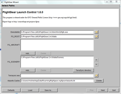
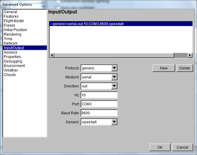
On Windows, just launch it from the Start menu, enter the details of your FlightGear installation (see below), follow the wizard's prompts and pick an aircraft and an airport, and at the end click on Advanced..., choose Input/Output, click new and adjust the settings so that they match the following screenshot:
And check out your FlightSimInstrument!
(You might need to use the knob next to the altimeter in FlightGear to initialise it while you're on the runway before you take off)
Iteration 1 summary
Here's the program:
Import programFlightSimInstrument-1
This project is about creating an airplane instrument (such as an altimeter) for a flight simulator running on a PC. The code will read in two space-separated \"words\" containing the altitude and airspeed, with units, from a \"USBSerial port\". See my notebook page for details.
And here's your flightgear command:
fgfs --generic=file,out,10,/dev/serial/by-id/usb-mbed.org_CDC_DEVICE_0123456789-if00,speedalt
or serial equivalent (see windows screenshot)/use wizard.
Iteration 1.5: USBSerial : PC - getting data from a self-written program
Using Python's PySerial, the following code will send some data to the mbed:
import serial
ser = serial.Serial("/dev/serial/by-id/usb-mbed.org_CDC_DEVICE_0123456789-if00")
ser.write("200kt 4500ft\n")
ser.close()
So, adding a UDP server around that:
#!/usr/bin/env python

# Slightly hacky Python script to forward data from FlightGear to the mbed.
import SocketServer
import serial

class FlightSimInstrumentUDPHandler(SocketServer.BaseRequestHandler):
    """
    This class will handle UDP packets sent to a SocketServer, forwarding
    the data to the mbed for display.
    If you need to, you could call XML parsers etc here to transform the data
    such that the mbed understands it (do this in the handle method).
    """

    def handle(self):
        global serial_port
        data = self.request[0].strip()
        socket = self.request[1]
        print "{} wrote:".format(self.client_address[0])
        print data
        serial_port.write(data + "\n")


if __name__ == "__main__":
    HOST, PORT = "localhost", 9999
    SERIAL_DEVICE = "/dev/serial/by-id/usb-mbed.org_CDC_DEVICE_0123456789-if00"
    # Open serial port
    global serial_port
    serial_port = None
    try:
        serial_port = serial.Serial(SERIAL_DEVICE)
    except serial.SerialException as e:
        print e
        exit(1)

    # Start UDP server
    server = SocketServer.UDPServer((HOST, PORT),
                                    FlightSimInstrumentUDPHandler)
    try:
        print "Server ready."
        server.serve_forever()
    except KeyboardInterrupt:
        print "Keyboard interrupt received, shutting down..."
        serial_port.close()
... and you can now send the data from FlightGear in the same format over UDP to the Python program, and it will be displayed on the mbed. To launch FlightGear in a way that it sends data via UDP, use the following command (or adapt the Input/Output screen in the Windows wizard); if you need more details, check the generic protocol FG wiki page:
fgfs --generic=socket,out,10,127.0.0.1,9999,udp,speedalt
And of course execute your python script, too.
Why would you want to do this? Well, most programs won't have convenient "export data to serial" capabilities... Here, it's probably not really necessary, but I showed it just in case you want to expand on this.
I originally intended to make a version of this project, that would be using the USB HID interface, but decided to try that from a Crysis mod instead.
Feel free to post any feedback in the comments!
Please log in to post comments.

