Smart Alarm
Aiming at solving the everyday problem of getting up, Smart Alarm is a waking-up system that can monitor the sleeping activities of the user and perform different functionalities to help the user getting out of bed.
System Features
- Accelerometric sleep cycle tracking: data saved to SD card and sent to Android
- Sleep cycle detection and smart early wake-up: detect light sleep and deep sleep
- Gentle wake up and smart light automation: light dimness can be adjusted
- Anti-oversleeping and actually get the user out of bed: reading of the load sensor underbed will be monitored
Please refer to below for more detailed information regarding the Smart Alarm project.
How It Works
The Smart Alarm system is composed of both hardware and software components: mbed is wired with relay, load sensor, and accelerometer sensor, speaker; the Android application which runs on the user's Android phone
Three major components of the Smart Alarm Project:
- mbed wired with bluetooth, sensors, relay, and speaker
- Android application
- Bluetooth connection between mbed and Android
Basically, Smart Alarm operates according to the following: Firstly, the user has to set up an alarm on his/her Android phone, and click the START button on the menu option to start establishing connection with the mbed. After the connection establishment, the Android application will automatically receiving accelerometer readings from mbed through bluetooth connection and plot a dynamic sleep graph on the user interface of the Android application. With well-designed algorithm, mbed is able to detect the most approprite wake up time 15 minutes before the preset alarm time. If the user movement has been active, the system will perform an early wake up by start playing soft music and gradually turning up the light. When it reaches the pre-set alarm time, the system will wake up the user in a more forceful manner: the light will be gradually turning up through relays and alarm on mbed will be ringing through speaker. If the user attempts to turn off the alarm on phone and get back to bed, the pressure/load sensors set under bed will sense the change in pressure and act accordingly. The alarm will keep ringing until the user physically gets off bed for a while.
Schematic
Below is a picture taken of the schematic.
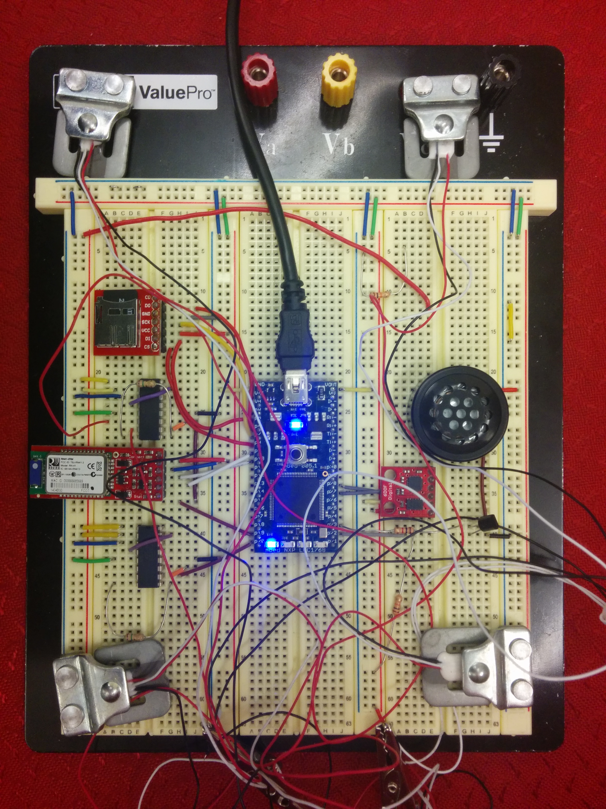
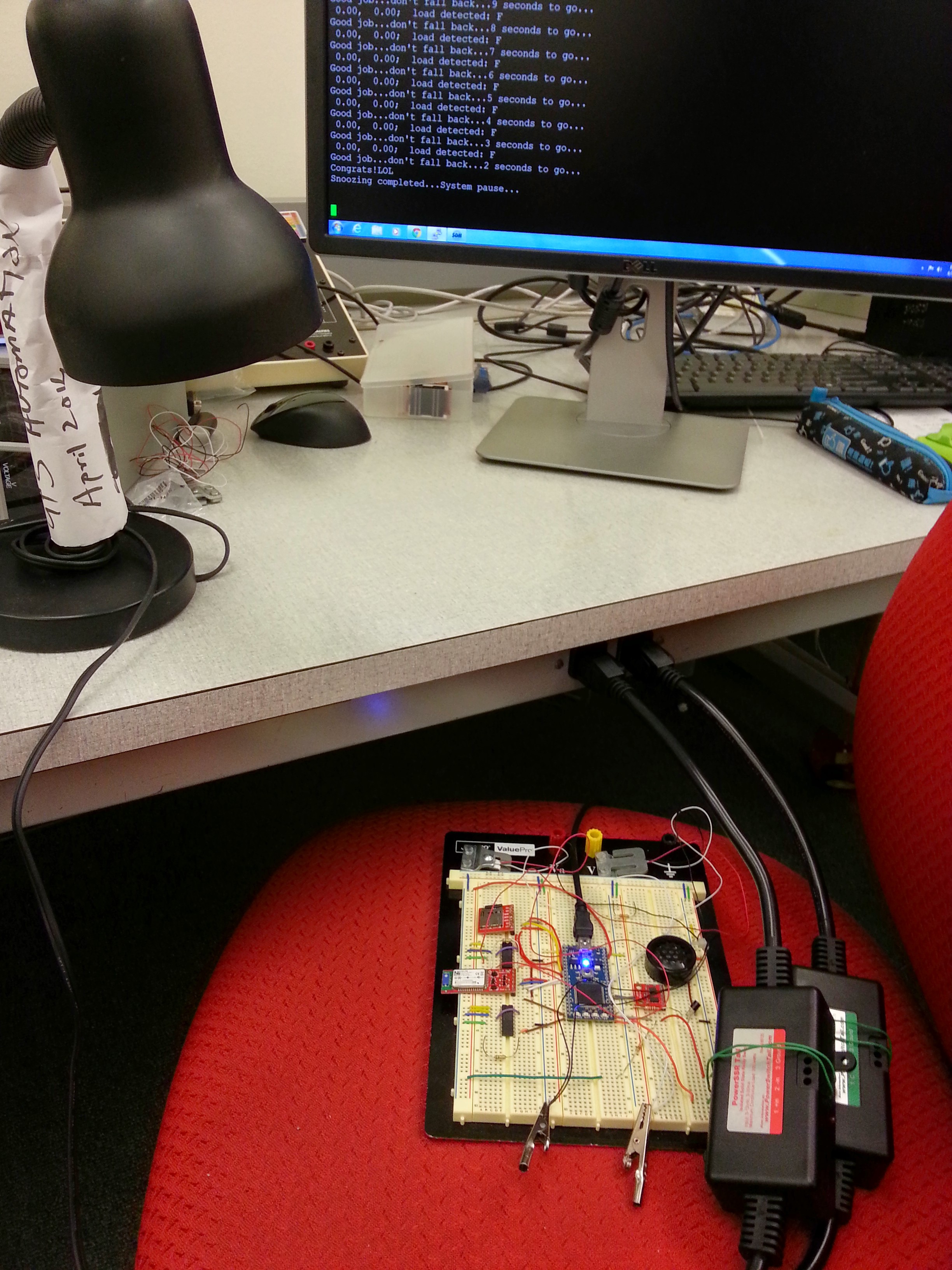
The entire system prototype is shown below.
Modules and Datasheets
Bluetooth
Detailed information about the Bluetooth Modem - BlueSMiRF Gold as shown below.

Accelerometer
Tutorial of the IMU Digital Combo Board - 6 Degrees of Freedom ITG3200/ADXL345 can be found here. However in this project we are only using the ADXL345 accelerometer on it, the tutorial can be found here. Notice that the accelerometer on this breakout board uses the I2C interface.

Load Sensor
Detailed information about the Load Sensor - 50kg as shown below.

It's a bit tricky to hook things up, and here are some instructions.
Since the range of output from the load sensor is only several mV, we use a INA125P to get a usable value. Datasheet can be found (here).
It provides complete bridge excitation and precision differential-input amplification on a single integrated circuit. A single external resistor connecting pins 8 and 9 sets any gain from 4 to 10,000 with the relationship G = 4 + 60kOhm/R. Using a 10Ohm resistor will give you 0V-5V (or 5V to 0V if you wire it backwards), and in our project we use a 15Ohm resistor to get approximately 0V-3.3V for mbed's analog input pin.
Below shows a useful schematic.

It uses a 4-wire load sensor and is designed for the Arduino processor. However what we got here is a 3-wire load sensor, so we need two load sensors to build a wheatstone bridge. White wires go to V+, black wires to V-, and red wires go to pin 6 and 7 of the INA125P. Also we need to use a 15Ohm resistor instead of the 10Ohm one indicated in the above figure.
SD Card
Tutorial of the Breakout Board for microSD Transflash can be found here.

The one we got is pretty much like this except some slight differences in the pin layout.
PowerSSR and ZeroCross Tail
Tutorial of the PowerSSR Tail and ZeroCross Tail can be found here. The PowerSSR Tail and ZeroCross Tail are shown below.


Speaker Alarm
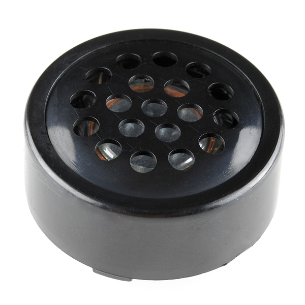
Here is how to use the speaker as an alarm.
Wiring
Here is the wiring for the demo program.
| mbed | microSD | Bluetooth | IMU | PowerSSR Tail | ZeroCross Tail |
|---|---|---|---|---|---|
| VOUT | VCC | VCC | 3.3V | ||
| GND | GND | GND | GND | 2 -in | 2 E |
| P5 | DI | ||||
| P6 | DO | ||||
| P7 | SCK | ||||
| P8 | CS (optional) | ||||
| P9 | RX-I | ||||
| P10 | TX-O | ||||
| P28 | SDA | ||||
| P27 | SCL | ||||
| P21 | 1 +in | ||||
| P22 | 1 C (pullup) |
Android Application
As an essential part of the Smart Alarm system, the Smart Alarm Android application is responsible for getting the correct user input when setting up the alarm time, performing early wake up by playing soft music, displaying sleeping activity plot, and etc.
The Smart Alarm Android application was tested on different phones with android API 4.0(Lenovo KB860), 4.3(Samsung S3), 4.4(Nexus 5), respectfully.
Smart Alarm Android application functionalities:
- displaying current time
- setting up alarm time with several options (e.g. Alarm on/off, One time/ Repeating Alarm)
- initiating bluetooth connection with paired devices
- plotting sleeping activity plot for user's information
- playing waking up music at both ealry wake up stage and preset alarm time
Several screen shots of the Smart Alarm Android application:
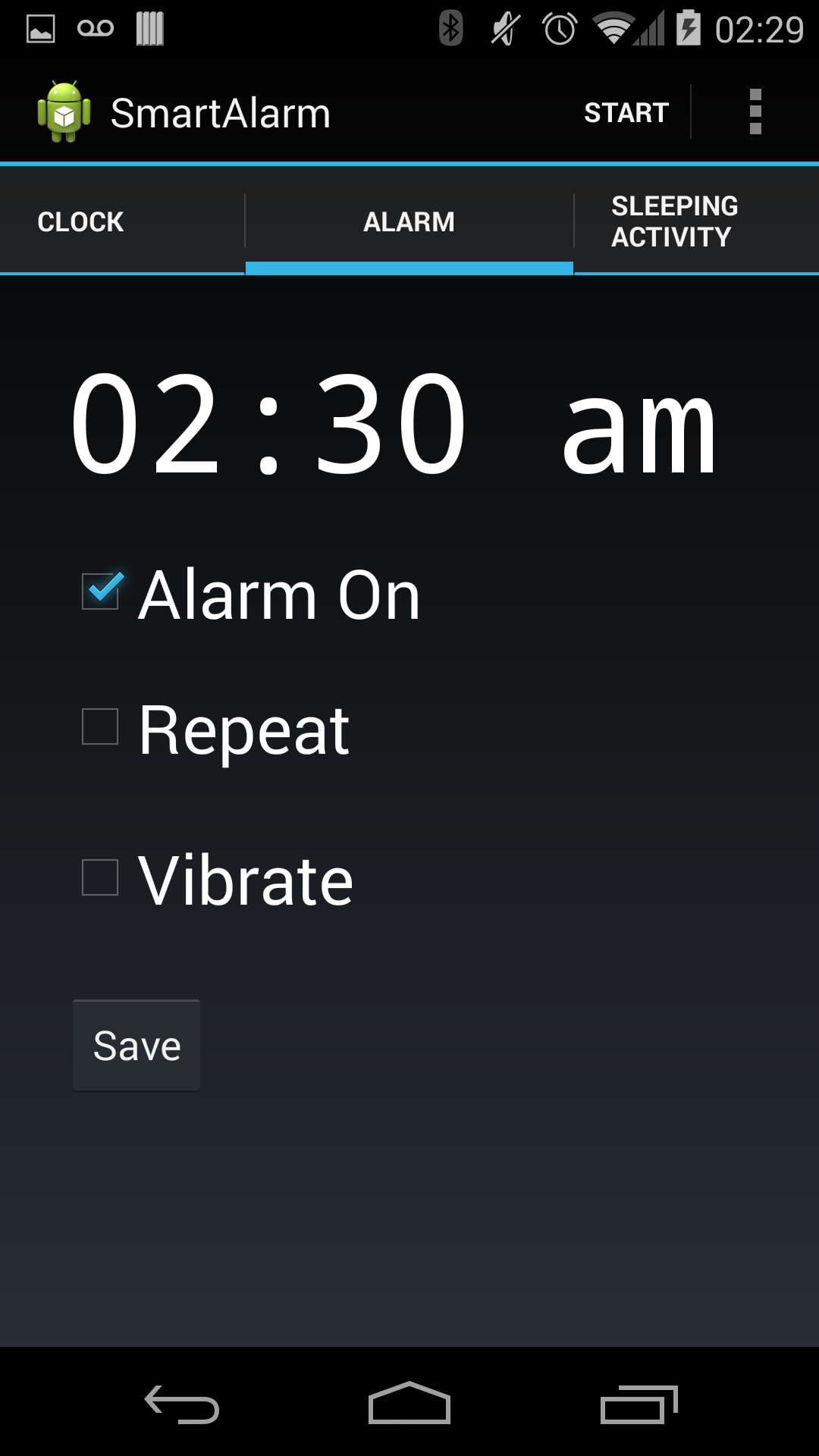
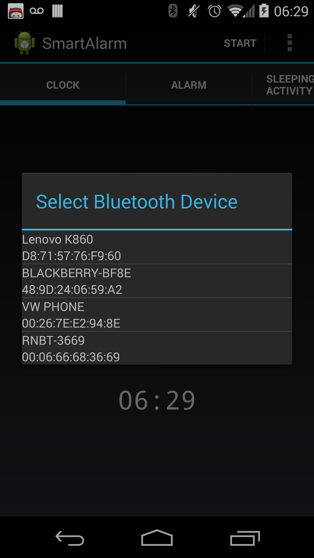
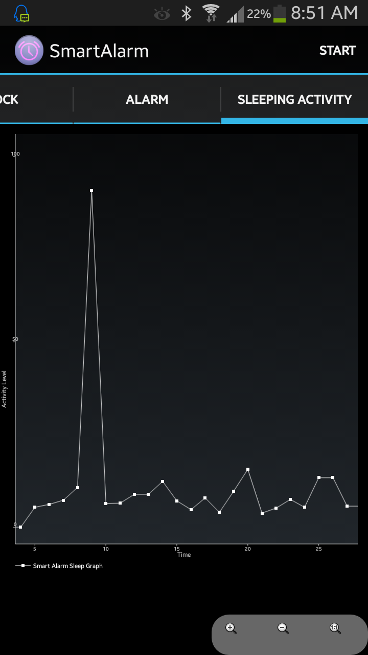
Screen #1 Clock showing current time, Screen #2 List of paired bluetooth device, Screen #3 Sleep Actigraphy
Sleeping Actigraphy
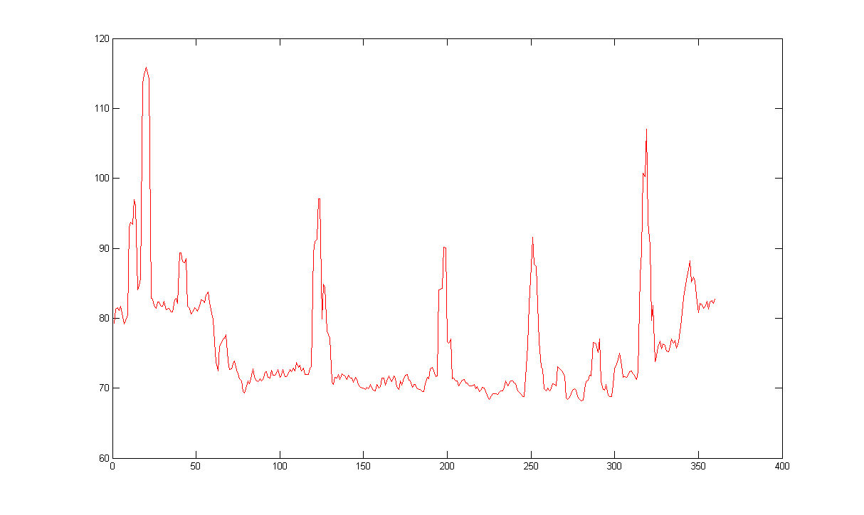
This is a sleeping activity graph is generated by sampling the peak value in every minute. Below is a real sleeping activity graph with data collected while one of our team member was sleeping. From the graph, it is easy to see the sleep cycles during a person's sleep. For our project, the team is also drawing a similar graph on the Android user interface for user's information.
Android APK
The APK of the Android application we developed for this project can be downloaded here. /media/uploads/ivygatech/smartalarm.apk
Demo
Watch the video to see how it works.
The project can be found below.
Import programSmartAlarm
Source code for project Smart Alarm (Georgia Tech ECE 4180)
Library
Below are all the libraries used in this project.
ADXL345_I2C
Import programADXL345_I2C
This library enables users to communicate with the ADXL345 accelerometer through the I2C bus on the mbed. The API names are similar and work nearly the same way as those made in the SPI libraries for the ADXL345.
SDFileSystem
Import librarySDFileSystem
SDFileSystem
Beep
Import librarybeep
Make noise with a piezo buzzer. Use a pwm pin.
Please log in to post comments.
