Using low cost Blackpill (STM32F411CEU6) boards with mbed.
Using Blackpill (STM32F401CCU6 or STM32F411CEU6) boards with mbed
It provides an affordable (about $3 / $6 on eBay) and flexible way for users to try out new ideas and build prototypes. The board is equipped with an STM32F401CCU6 or an STM32F411CEU6 microcontroller compatible with the NUCLEO-F401CE or the NUCLEO-F411RE platform, respectively.
Microcontroller features
- STM32F401CCU6 or STM32F411CEU6 in UFQFPN48 package
- ARM® 32-bit Cortex® -M4 CPU with FPU
- 100 MHz max CPU frequency
- VDD from 1.7 V to 3.6 V
- 256 or 512 KB Flash
- 64KB or 128 KB SRAM
- GPIO with external interrupt capability
- 1x12-bit, 2.4 MSPS ADC with 16 channels
- DMA Controller
- Up to 11 Timers (six 16-bit, two 32-bit, two watchdog timers and a SysTick timer)
- USART/UART (3)
- I2C (3)
- SPI/I2S (3 or 5)
- SDIO
- USB 2.0 full-speed device/host/OTG controller with on-chip PHY
- CRC calculation unit
- 96-bit unique ID
- RTC
Board features
- Small foot-print
- Flexible board power supply: USB VBUS or external source (3.3V, 5V)
- User LED: LED1
- Three push buttons: RESET, BOOT0, KEY
- Programming/Debug port
- USB-C connector
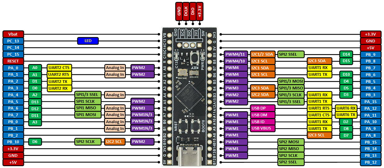
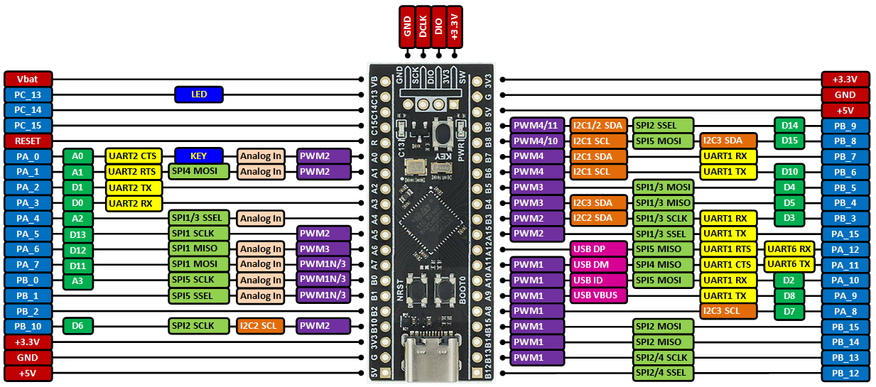
Board pinout
When equipped with STM32F401CCU6:
When equipped with STM32F411CEU6:
For more details on pin definitions see Table 8 in the Datasheet.
Information
Only the labels printed in blue/white or green/white (i.e. PC_13, PB_9, A0, D14 ...) must be used in your code. The other labels are given as information (alternate-functions, power pins, ...). You can also use these additional pin names:
Please notice that in order to fit the small size board, the leading 'P' and the '_' characters are omitted from labels indicated on the board (e.g. Instead of 'PA_1' you can find the label 'A1' on the board). Arduino (green/white) and the additional naming labels are not indicated on the board.
Also notice that the on-board LED is connected to pin PC_13 and, via a resistor, to +3.3V. So to turn the LED on or off you have to set the DigitalOut to 0 or 1 respectively (active on 0).
Using the mbed online compiler to build programs for the Blackpill board
Create a program as if it was for a NUCLEO-F401RE or NUCLEO-F411RE board (select NUCLEO-F401RE or NUCLEO-F411RE as target platform for the online compiler).
Or click here to import this demo into your online compiler.
Blinking on-board LED:
#include "mbed.h"

DigitalOut led(PC_13);

int main()
{
    while (true) {
        led = !led;
        ThisThread::sleep_for(500ms);
    }
}
Building programs with Mbed Studio IDE
The Mbed Studio IDE is a great tool for working offline.
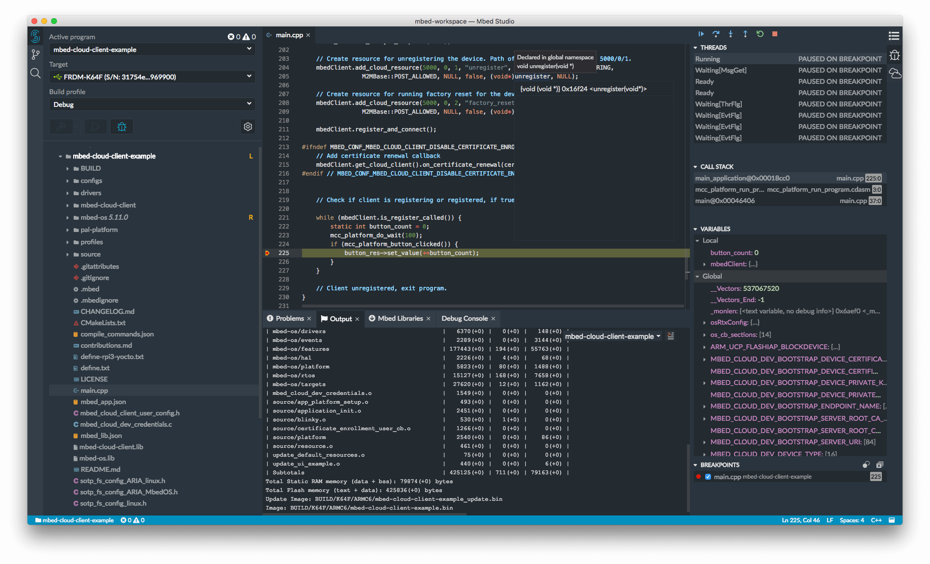
- It supports Mbed OS 6 (with built-in Mbed RTOS threads, mutexes, semafores ...)
- and also Mbed OS 6 Bare metal profile (no RTOS, similar to Mbed OS 2) which is suitable for small or medium size projects requiring less RAM and Flash. To use it, add a
mbed_app.jsonconfiguration file to your project:
med_app.json
{
    "requires": ["bare-metal"]
}
As target you can select
- either the NUCLEO_F401RE or the NUCLEO_F411RE
- or the BLACKPILL custom target.
Advantages of the BLACKPILL custom target over the NUCLEO_F401RE/ NUCLEO_F411RE
- The onboard external 25 MHz crystal is used as system clock source rather than the less precise internal 16 MHz RC oscillator.
- The onboard LED works as LED1 in programs.
- The onboard KEY on STM32F411CEU6 boards works as USER_BUTTON pin in programs.
- You can use the USB peripheral in your programs and connect the board to the PC over the onboard USB connector. An example of using the USB peripheral as USBSerial (12 Mbit/s) is available here.
Building programs for the BLACKPILL custom target in Mbed Studio
- Connect an STM32 ST-Link programmer to your BLACKPILL board and PC (see below for more details).
- Create a new program in the Mbed Studio IDE.
- Right-click on the program's root folder and in the popup window select
Add library...
- Copy&paste the text https://os.mbed.com/users/hudakz/code/BLACKPILL_Custom_Target into the
Git or os.mbed.com URLedit box and click on theNextbutton.
- Open the drop-list and select
defaultasBranch or tagand click on theFinishbutton.
- Open the
BLACKPILL_Custom_Targetfolder and according to you board drag&drop theTARGET_BLACKPILL_F401CCor theTARGET_BLACKPILL_F411CEfolder and thecustom_targets.jsonfile one by one to the root folder of your program.
- Delete the
BLACKPILL_Custom_Targetfolder from your project. (Right-click and select delete).
- Open the
Targetdrop-list and click on the button with a "chip" icon on it (Manage custom targets) .
- Open the
USB devicedrop-list and select your STM32 ST-Link programmer.
- Open the
Build targetdrop-list and according to your board selectBLACKPILL_F401CCorBLACKPILL_F411CE.
- Click on the
Save Allbutton.
- Build your program (click on hammer button).
Programming the Blackpill board
NUCLEO ST-LINK/V2-1 and drag & drop
You can use the NUCLEO virtual disk to program the Blackpii board (drag and drop programming). To do that, an additional NUCLEO board is needed (any type equipped with ST-LINK/V2-1 will do).
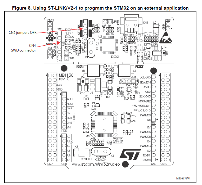
- Remove the two jumpers from the CN2 connector as illustrated in Figure 8:
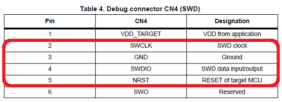 | 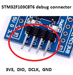 |
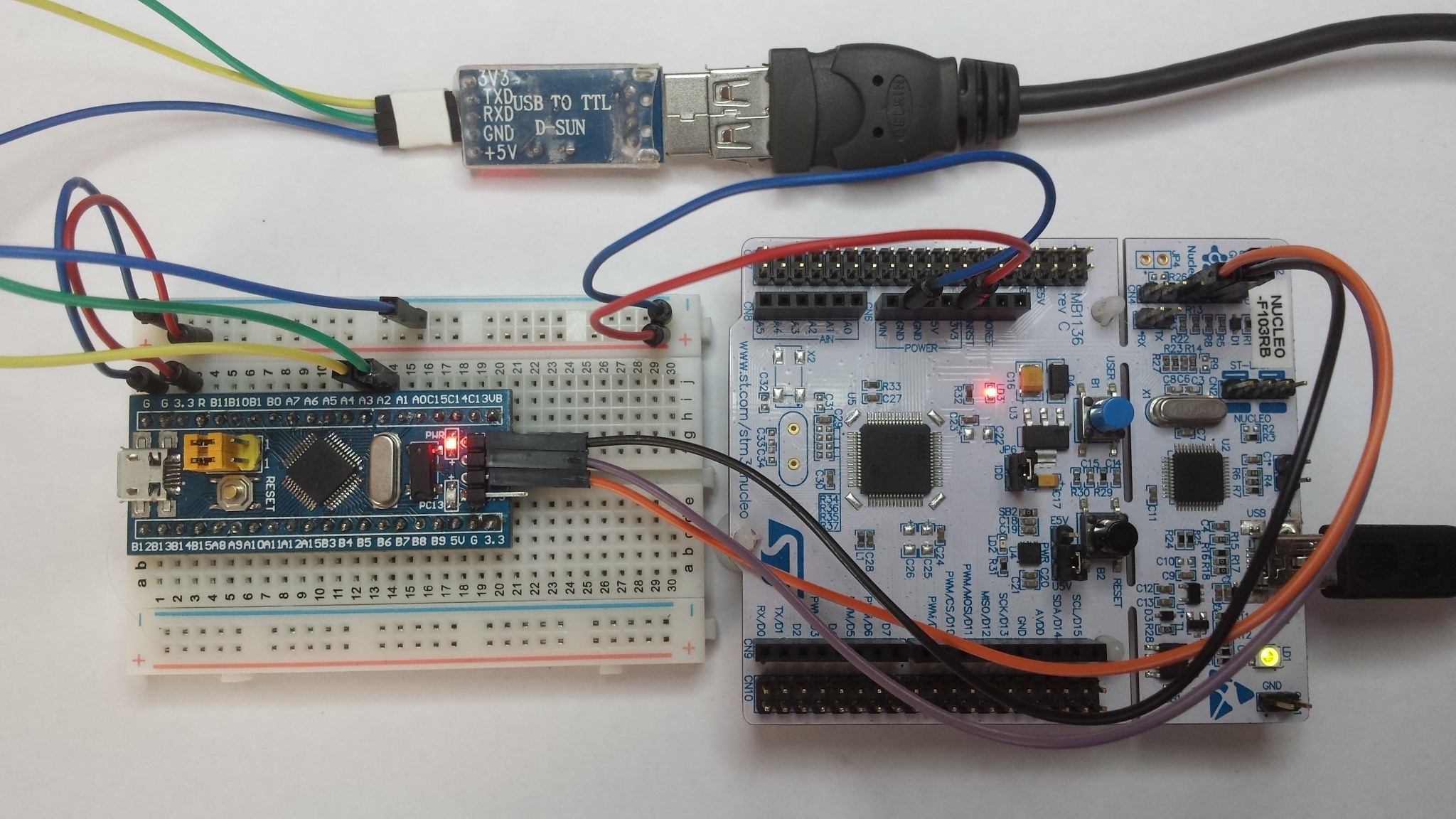
- Connect the NUCLEO board CN4 connector to the Blackpill board using flying wires as follows:
| NUCLEO board CN4 connector | Blackpill debug connector | Blackpill board | |||||
|---|---|---|---|---|---|---|---|
| SWCLK | <=> | DCLK | |||||
| GND | <=> | GND | |||||
| SWDIO | <=> | DIO | |||||
| NRST | <=> | RESET |
Warning
Please notice that VDD_TARGET is not connected. That works with the ST-Link programmer but could potentially damage the target micro controller in case it's running at a lower voltage (e.g. 2V5) than the programmer (e.g. 3V3). That's why it's recommended to connect also the VDD_TARGET line when an external programmer such as a Segger J-Link is hooked up to program the board.
- Provide power for the Blackpill board through a 3.3V pin, 5V pin or over a USB cable. (The VDD_TARGET pin on the NUCLEO board CON4 does not work as source of power).
- Connect the NUCLEO board to your PC over a USB cable.
- To program the Blackpill board, click on the Compile button and save the binary to the NUCLEO virtual disk .
For more details have a look at the User Manual, chapter 6.2.4 Using ST-LINK/V2-1 to program and debug an external STM32 application.
ST-Link V2 USB dongle and STM32 ST-LINK utility
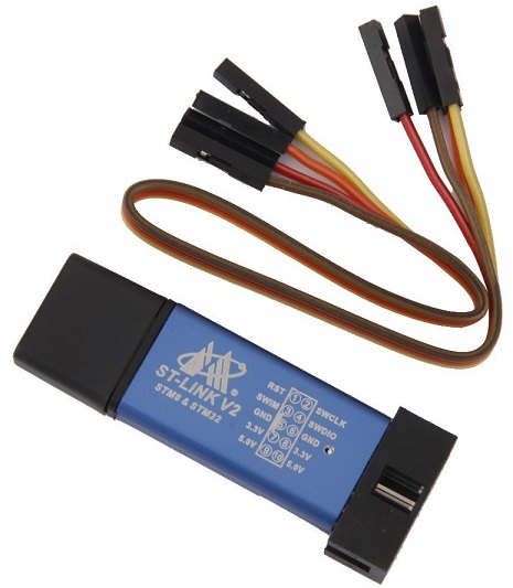
If you would like to use an ST-Link V2 USB dongle (aka ST-Link V2 Programming Unit) to program the board apply the same wiring as specified above. If not done yet install an ST-Link/V2 driver onto your PC. Plug the ST-Link V2 dongle into your PC. Then click on the Compile button and save the binary to your local disk. Install and run the STM32 ST-LINK utility. Once the program is running open the binary built with the online compiler and click on the Program verify button.
STM32 USART system memory bootloader and Flasher-STM32
Have a look at STM32 Embedded Bootloader.
Download: FLASHER-STM32
For more details read:
Appliction Note AN2606.
Using serial port (not just for debugging)
- Connect an FTDI or similar USB to Serial TTL converter to your PC and to an on-board serial port (for example PA_2, PA_3). Make sure you connect the on-board TX pin to the converter's RX pin and the on-board RX pin to the converter's TX pin.
- In your code, create a
Serialobject (using TX and RX pin names of the connected serial port).
- Use
printffunction to send serial messages to the connected PC.
Sending debug messages over the ST-Link virtual com port
In case you would like to spare the external USB-Serial converter for other purposes then there is available an alternative solution proposed by X M (bitman). You can use the ST-Link virtual com port also for debugging of programs running on the Blackpill board. However, that will require a soldering iron (and probably some soldering skills). According to the User Manual, chapter 6.8 "USART communication", solder bridges (on the back side of the NUCLEO board) SB62 and SB63 should be ON, SB13 and SB14 should be OFF. In such case it is possible to connect another USART to the NUCLEO (ST-Link) CN3 connector using flying wires. For instance on Blackpill board it is possible to use USART2 available on PA_2 (TX) and PA_3 (RX). Two flying wires shall be connected as follows:
| Blackpill board, pin PA_2 (Serial2 TX) | <=> | NUCLEO board CN3 connector, pin RX |
| Blackpill board, pin PA_3 (Serial2 RX) | <=> | NUCLEO board CN3 connector, pin TX |
A smart trick proposed by Nothing Special makes even soldering needless.
The point is to redirect the UART on the NUCLEO board by software (without modifying the solder bridges on the back side of the NUCLEO board) and convert it into a "Debugger". On the NUCLEO board that you are going to use as programmer/ debugger, choose any Serial port other than Serial2 (other than the default port used for standard UART) to be initialized as standard UART. In the program below (using NUCLEO-F103RB as programmer/debugger) Serial1 (PA_9, PA_10) was selected.
Debugger
#include "mbed.h"

// declarations needed to change the parameters of stdio UART
extern serial_t     stdio_uart;
extern int          stdio_uart_inited;

int main() {
    serial_init(&stdio_uart, PA_9, PA_10); // other than Serial2
    stdio_uart_inited = 1;
    printf("Ready for debugging\r\n");
}
Once compiled (remember to select the NUCLEO board used for programing/debugging as target for the online compiler), download the "Debugger" program to the NUCLEO board. Please make sure you have the two jumpers in place on the CN2 connector when programming the NUCLEO board. Once the "Debugger" binary has been downloaded to the NUCLEO board, remove the two jumpers again.
Happy coding :-)
README.md
- Committer:
- hudakz
- Date:
- 2020-09-23
- Revision:
- 0:a12913077fa8
File content as of revision 0:a12913077fa8:

# Blinky Mbed OS example
The example project is part of the [Arm Mbed OS Official Examples](https://os.mbed.com/code/) and is the [getting started example for Mbed OS](https://os.mbed.com/docs/mbed-os/v5.14/quick-start/index.html). It contains an application that repeatedly blinks an LED on supported [Mbed boards](https://os.mbed.com/platforms/).
You can build the project with all supported [Mbed OS build tools](https://os.mbed.com/docs/mbed-os/latest/tools/index.html). However, this example project specifically refers to the command-line interface tool [Arm Mbed CLI](https://github.com/ARMmbed/mbed-cli#installing-mbed-cli).
(Note: To see a rendered example you can import into the Arm Online Compiler, please see our [import quick start](https://os.mbed.com/docs/mbed-os/latest/quick-start/online-with-the-online-compiler.html#importing-the-code).)
1. [Install Mbed CLI](https://os.mbed.com/docs/mbed-os/latest/quick-start/offline-with-mbed-cli.html).
1. Clone this repository on your system, and change the current directory to where the project was cloned:
```bash
$ git clone git@github.com:armmbed/mbed-os-example-blinky && cd mbed-os-example-blinky
```
Alternatively, you can download the example project with Arm Mbed CLI using the `import` subcommand:
```bash
$ mbed import mbed-os-example-blinky && cd mbed-os-example-blinky
```
## Application functionality
The `main()` function is the single thread in the application. It toggles the state of a digital output connected to an LED on the board.
## Building and running
1. Connect a USB cable between the USB port on the board and the host computer.
2. <a name="build_cmd"></a> Run the following command to build the example project and program the microcontroller flash memory:
```bash
$ mbed compile -m <TARGET> -t <TOOLCHAIN> --flash
```
The binary is located at `./BUILD/<TARGET>/<TOOLCHAIN>/mbed-os-example-blinky.bin`.
Alternatively, you can manually copy the binary to the board, which you mount on the host computer over USB.
Depending on the target, you can build the example project with the `GCC_ARM`, `ARM` or `IAR` toolchain. After installing Arm Mbed CLI, run the command below to determine which toolchain supports your target:
```bash
$ mbed compile -S
```
## Expected output
The LED on your target turns on and off every 500 milliseconds.
## Troubleshooting
If you have problems, you can review the [documentation](https://os.mbed.com/docs/latest/tutorials/debugging.html) for suggestions on what could be wrong and how to fix it.
## Related Links
* [Mbed OS Stats API](https://os.mbed.com/docs/latest/apis/mbed-statistics.html).
* [Mbed OS Configuration](https://os.mbed.com/docs/latest/reference/configuration.html).
* [Mbed OS Serial Communication](https://os.mbed.com/docs/latest/tutorials/serial-communication.html).
* [Mbed OS bare metal](https://os.mbed.com/docs/mbed-os/latest/reference/mbed-os-bare-metal.html).
* [Mbed boards](https://os.mbed.com/platforms/).
### License and contributions
The software is provided under Apache-2.0 license. Contributions to this project are accepted under the same license. Please see contributing.md for more info.
This project contains code from other projects. The original license text is included in those source files. They must comply with our license guide.
