Library for Mini-DK board
Dependents: LPC1768_Mini-DK_EasyWeb_DM9161 LPC1768_Mini-DK LPC1768_Mini-DK
Fork of Mini-DK by
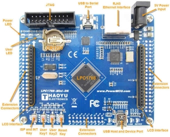
Mini-DK board overview (Micro SD connector is at the bottom side)
One serial interface , uses CP2102 (USB to RS232 interface, support ISP download )
RJ45-10/100M Ethernet network interface (Ethernet PHY: DM9161)
2.8 inch TFT color LCD interface (SPI interface or 16Bit parallel interface)
Touch panel controller XPT2046 (ADS7843 compatible)
USB 2.0 interface, USB host and USB Device interface.
TF SD / MMC card (SPI) interface.
Two user buttons, One Reset button and ISP button , One INT0 button, two user-programmable LED lights
Serial ISP download, Standard 20-pin JTAG download simulation debugging interface.
Selection between external 5V power supply or USB 5V supply.
Board size: 95mm * 78mm
All IO available on extension connectors

04/01/13
Erik Olieman (http://mbed.org/users/Sissors/) joined the code development for the Mini-DK board.
Thanks to his input, we were able to obtain a tremendous speed gain, remove warnings, ...
An overview of all modifications is stored in modifs.h
The old page (http://mbed.org/users/frankvnk/code/LPC1768_Mini-DK/) contains the demo code.
IMPORTANT : Due to a change in the mbed libraries (Stream()), we cannot use the printf instruction - we need to use <SPI_TFT>.printf (example - see main.cpp in http://mbed.org/users/frankvnk/code/LPC1768_Mini-DK/)
WARNING: filetoflash (SD to CPU flash)
The SPI_TFT library contains an option to copy an image from the SD card to the CPU flash memory. This allows you to use an image as background without speed loss when writing other text and graphics.
By default, this option is enabled.
It can be disabled by uncommenting the #define mentioned below in Mini_DK.h:
#define NO_FLASH_BUFFER
Since the flash memory has limited write endurance, DO NOT use this feature when you intend to read multiple images from the SD card (eg: when used as a photo frame).
14/01/13
A newer version of the Mini-DK has been released by the manufacturer: Mini-DK2. They replaced the DM9161 PHY with a LAN8720A PHY and better buttons are fitted on the board. All other hardware remains the same. Code for this PHY is available from the NXP MCU SW application team. This allows us to use the mbed 'EthernetInterface' library with little modifications. Further info - see http://mbed.org/forum/mbed/topic/3684/?page=1#comment-18473.
Notes:
The code in 'lpc_phy_lan8720.c' uses 'msDelay' - needs to be replaced with 'osDelay'.
A custom MAC address can be defined using following code:
extern "C" void mbed_mac_address(char * mac) {

// define your own MAC Address
  mac[0] = 0x00;
  mac[1] = 0x01;
  mac[2] = 0x02;
  mac[3] = 0x03;
  mac[4] = 0x04;
  mac[5] = 0x05;

};
TouchADS7843/Touch.h
- Committer:
- frankvnk
- Date:
- 2013-01-04
- Revision:
- 8:9517c10e40d2
- Parent:
- Mini-DK/TouchADS7843/Touch.h@ 7:ffdd4e75b366
- Child:
- 18:f045ae645960
File content as of revision 8:9517c10e40d2:
/******************************************************************
 *****                                                        *****
 *****  Name: Touch.h                                         *****
 *****  Ver.: 1.0                                             *****
 *****  Date: 04/01/2013                                      *****
 *****  Auth: Frank Vannieuwkerke                             *****
 *****        Erik Olieman                                    *****
 *****  Func: Touch driver for use with ADS7843               *****
 *****                                                        *****
 ******************************************************************/

#ifndef MBED_Touch_H
#define MBED_Touch_H

#include "SPI_TFT.h"
#include "mbed.h"

    typedef struct
    {
       int x;
       int y;
    } Coordinate;

    typedef struct
    {
    int         An,
                Bn,
                Cn,
                Dn,
                En,
                Fn,
                Divider ;
    } Matrix;

class TouchScreenADS7843 {
public:
    Coordinate  display;
    Coordinate  screen;

    /*
    * Create a Touchscreen object connected to SPI and two pins
    *
    * @param mosi,miso,sclk SPI
    * @param cs pin connected to CS of ADS7843
    * @param irq pin connected to IRQ of ADS7843
    * @param pointer to SPI_TFT constructor
    *
    */
    TouchScreenADS7843(PinName tp_mosi, PinName tp_miso, PinName tp_sclk, PinName tp_cs, PinName tp_irq, SPI_TFT *_LCD);

    /*
    * Draw a 2 by 2 dot on the LCD screen
    *
    * @param x (horizontal position)
    * @param y (vertical position)
    * @param color (16 bit pixel color)
    *
    */
    void TP_DrawPoint(unsigned int Xpos,unsigned int Ypos,unsigned int color);

    /*
    * Obtain averaged data from ADS7846
    * does 9 consecutive reads and only stores averaged data
    * when the 9 points are within the treshold limits.
    *
    * @param screenPTR (pointer to store data)
    * @returns 1 on success
    * @returns 0 on failure
    *
    * If called with screenPTR = NULL - 'screen' variable is used, otherwise (parameter) is used.
    *
    */
    unsigned char Read_Ads7846(Coordinate * screenPtr = NULL);

    /*
    * Calibrate the touch panel.
    * Three crosshairs are drawn and need to be touched in sequence.
    * A calibration matrix is set accordingly.
    *
    */
    void TouchPanel_Calibrate(void);

    /*
    * Obtain real x,y coordinates
    * The x,y coordinates are calculated using the calibration matrix.
    *
    */
    unsigned char getDisplayPoint(void);

    SPI_TFT    *LCD;
    SPI        _tp_spi;
    DigitalOut _tp_cs;
    DigitalIn  _tp_irq;

protected:

    #define    SPI_RD_DELAY    1
    #define    CHX             0xd0    // 12 bit mode
    #define    CHY             0x90

    Coordinate DisplaySample[3];
    Coordinate ScreenSample[3];
    Matrix matrix;

    /*
    * Obtain raw x,y data from ADS7846
    *
    * @param pointer to raw x and y coordinates (pointer to store data)
    * @returns x (horizontal position)
    * @returns y (vertical position)
    *
    */
    void TP_GetAdXY(int *x,int *y);

    /*
    * Obtain raw single channel data from ADS7846 (Called by TP_GetADXY)
    *
    * @param channel to be read (CHX or CHY)
    * @returns raw scaled down value (return value range must be between 0 and 1024)
    *
    */
    int Read_XY(unsigned char XY);

    /*
    * Draw a calibration crosshair on the LCD screen
    *
    * @param x (horizontal position)
    * @param y (vertical position)
    *
    */
    void DrawCross(unsigned int Xpos,unsigned int Ypos);

    /*
    * Set the calibration matrix
    *
    * @param displayPTR (pointer to display data)
    * @param screenPTR  (pointer to screen data)
    * @param matrixPTR  (pointer to calibration matrix)
    *
    * @returns 0 when matrix.divider != 0
    * @returns 1 when matrix.divider = 0
    *
    */
    unsigned char setCalibrationMatrix( Coordinate * displayPtr,Coordinate * screenPtr,Matrix * matrixPtr);

};
#endif


