Important changes to repositories hosted on mbed.com
Mbed hosted mercurial repositories are deprecated and are due to be permanently deleted in July 2026.
To keep a copy of this software download the repository Zip archive or clone locally using Mercurial.
It is also possible to export all your personal repositories from the account settings page.
ESP32 mbed Application Board
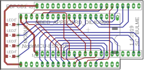
mbed Application board for ESP32 Node32s board.
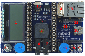
As described in Notes the application board has been designed to enable the maximum number of potential experiments and projects, with the minimum footprint.

With the addOn board the ESP32 board NodeMCU32s can be used.

Feature list
- 128x32 Graphics LCD
- 5 way joystick
- 2 x Potentiometers
- 3.5mm Audio jack (Analog Out)
- Speaker, PWM connected
- 3 Axis +/1 1.5g Accelerometer
- 3.5mm Audio jack (Analog In)
- 2 x Servo motor headers
- RGB LED, PWM connected
- USB-mini-B Connector
- Temperature sensor
- Socket for for Xbee (Zigbee) or RN-XV (Wifi)
- RJ45 Ethernet Connector
- USB-A Connector
- 1.3mm DC Jack input
Following the feature list there are some examples. For a more detailed description see ESP32-Software
128x32 LCD
An Arduino ESP32 example program to print text to the LCD
mbedEsp32S_LCD_SPI_HelloWorld.ino
#include <U8g2lib.h>
U8G2_ST7565_NHD_C12832_F_4W_HW_SPI u8g2(U8G2_R2, 5, 14, 13); // rotation = 180° = U8G2_R2 // VSPImosi(GPIO23), VSPIclk(GPIO18)

char buff[20];

void setup(void) {
  u8g2.begin();
}

void loop(void) {
  sprintf(buff, "Hello World");
  u8g2.setFont(u8g2_font_ncenB08_tr);
  u8g2.drawStr(0,30,buff);
  u8g2.sendBuffer();
}
Joystick
An example program for the mbed application board that uses the joystick button. LED1,2,3,4 light in sequence with up, down, left, right.
mbedESP32_PinArrays.ino
int ledPins[] = { 19, 17, 16,  4 }; // an array of pin numbers to which LEDs are attached
int joyPins[] = { 33, 26, 32, 27 }; // an array of pin numbers to which the JoyStick is attached
int pinCount = 4;                   // the number of pins (i.e. the length of the array)
int reading, prev, led;

void setup() {
  for (int thisPin = 0; thisPin < pinCount; thisPin++) {
    pinMode(ledPins[thisPin], OUTPUT);
    pinMode(joyPins[thisPin], INPUT_PULLDOWN);
    digitalWrite(ledPins[thisPin], HIGH);
  }
}

void loop() {
  for (int thisPin = 0; thisPin < pinCount; thisPin++) {
    reading = digitalRead(joyPins[thisPin]);
    if(reading == HIGH) {
      prev = led;
      led = thisPin;
    }
    digitalWrite(ledPins[led], LOW);
    digitalWrite(ledPins[prev], HIGH);
  }
}
Potentiometers
Sends ADC values between 0 and 4095 to serial port, so open Tools->Serial Monitor with 115200 baud:

mbedESP32_ADC_Poti1-2.ino
uint8_t ADC6 = 34;
uint8_t ADC7 = 35;
uint16_t adcPoti2, adcPoti1;

void setup() {
  Serial.begin(115200);
  Serial.println("\n DAC\mbed\tPoti1->ADC5(P33)\tPoti2->ADC4(P32)");
}

void loop() {
  adcPoti2 = analogRead(ADC6);
  adcPoti1 = analogRead(ADC7);
  Serial.printf("ADC: Poti1=%04d\tPoti2=%4d\n", adcPoti1, adcPoti2);
  delay(500);
}
See also ADC-Poti|ADC-Poti
Analog Out
ToDo: 3.5mm Audio jack not connected.
Speaker
A frequency sweeps up and down.
mbedESP32S_Speaker-PWM.ino
const int speaker = 12;     // 12 corresponds to GPIO26

const int freq = 5000;      // setting PWM properties
const int spkrChannel = 0;
const int resolution = 8;

void setup(){
  ledcSetup(spkrChannel, freq, resolution);
  ledcAttachPin(speaker, spkrChannel);
}

void loop(){
  for(int dutyCycle = 0; dutyCycle <= 255; dutyCycle++){
    ledcWrite(spkrChannel, dutyCycle);
    delay(15);
  }
  for(int dutyCycle = 255; dutyCycle >= 0; dutyCycle--){
    ledcWrite(spkrChannel, dutyCycle);
    delay(15);
  }
}
See i.e. https://os.mbed.com/users/4180_1/notebook/using-a-speaker-for-audio-output/
3 Axis +/1 1.5g Accelerometer
MMA7660FC_Demo.ino
See this [[https://os.mbed.com/users/fpucher/code/ESP32/wiki/I2C-Axis-Accelerometer|site]] for a description.

#include <Wire.h>
#include "MMA7660.h"

MMA7660 accelemeter;

void setup() {
  accelemeter.init();
  Serial.begin(9600);
}

void loop() {
  int8_t x, y, z;
  float ax,ay,az;
  enum {BufSize=50};
  char buf [BufSize];
  float myFloat = -1.012;

  Serial.println("******************************************");
  accelemeter.getXYZ(&x,&y,&z);
  snprintf (buf, BufSize, "x=%d y=%d z=%d", x, y, z);  // snprintf is safer than sprintf
  Serial.println(buf);
  accelemeter.getAcceleration(&ax,&ay,&az);
  snprintf (buf, BufSize, "ax: %.2fg  ay: %.2fg  az: %.2fg", ax, ay, az);
  Serial.println(buf);
  delay(500);
}
Analog In
ToDo: 3.5mm Audio jack not connected.
Servo Motor
See mbed Servo
RGB LED
An example program that cycles the on board RGB LED through various colours.
mbedESP32_RGB_PWM.ino
const int mbedLED_R = 0;
const int mbedLED_G = 2;
const int mbedLED_B = 15;

// setting PWM properties
const int freq = 5000;
const int ledChannel_R = 0;
const int ledChannel_G = 2;
const int ledChannel_B = 15;
const int resolution = 8;

void setup(){
  // configure LED PWM functionalitites
  ledcSetup(ledChannel_R, freq, resolution);
  ledcSetup(ledChannel_G, freq, resolution);
  ledcSetup(ledChannel_B, freq, resolution);

  // attach the channel to the GPIO to be controlled
  ledcAttachPin(mbedLED_R, ledChannel_R);
  ledcAttachPin(mbedLED_G, ledChannel_G);
  ledcAttachPin(mbedLED_B, ledChannel_B);
}

void loop(){
  for(int dutyCycle = 0; dutyCycle <= 255; dutyCycle++){
    ledcWrite(ledChannel_R, dutyCycle);
    ledcWrite(ledChannel_G, 255-dutyCycle);
    ledcWrite(ledChannel_B, dutyCycle);
    delay(15);
  }
}
See also a very RGB-Led Program.
USB Device
N.A.
LM75B Temperature sensor
An example program to read the current temperature from the LM75B and sends it to the serial port.
mbedEsp32S_LM75B_I2C
#include <Wire.h>

#define LM75B_address 0x48          // A0=A1=A2=Low
#define temp_reg      0x00          // Temperture register
#define conf_reg      0x01          // Configuration register

double temp = 0.0;

void setup()
{
  Wire.begin();
  Serial.begin(115200);

  Wire.beginTransmission(LM75B_address);
  Wire.write(temp_reg);
  Wire.endTransmission();
}

void loop()
{
  delay(500);

  Wire.requestFrom(LM75B_address, 2);
  double tmp = (double((Wire.read()<<8)|Wire.read()) / 256.0);
  Serial.println(tmp);
}
For more information on I2C goto LM75B and I2C
Xbee socket
N.A.
Ethernet Interface
N.A.
USB Host
N.A.