Grove - 3 axis Accelerometer
Introduction
The "Grove - 3 axis Accelerometer" is a 3 axis accelerometer that is accessible via a digital I2C interface.
This accelerometer module is based on MMA7660FC chip and it can be used for sensor data changes, product orientation, and gesture detection through an interrupt pin (INT).
It is a very low power, low profile capacitive MEMS sensor.
An accelerometer is a device that will measure the static acceleration and the dynamic acceleration.
- Static acceleration force is generated by a gravitational pull. When measuring static acceleration with a capacitive accelerometer, the measurements would portray the angle of tilt at which the device is being held or suspended in relation to the Earth's gravitational pull.
- Dynamic acceleration force is generated by vibrations from movement. Measuring vibrations allows a capacitive accelerometer to determine in which direction the device is moving and at what speed.
Required Components
Product Specifications
- Digital Output (I2C)
- 3 axis motion/orientation sensing
- Acceleration Range: ±1.5g (1g = 9.8m/s^2)
- Sensitivity: 21.33 counts/g
- Working voltage: 3V - 5V
- Resolution: 6bit
How it works
There are many different kind of accelerometer, for example piezoelectric and capacitive accelerometers.
In our case this accelerometer is capacitive.
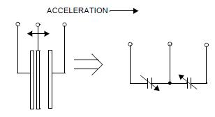
The sensor can be modeled as a movable beam that moves between two mechanically fixed beams (Figure below) and there is a certain capacitance between them.
If an accelerative force moves one of the structures, the capacitance will change.
In the end some circuits will convert the capacity into voltage.
Pin Description
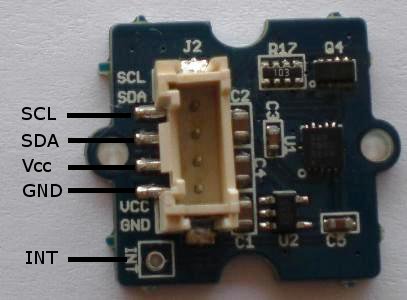
Connectivity
| HC05 pin | Mbed pin |
|---|---|
| 1 - SCL | P27 - SCL |
| 2 - SDA | P28 - SDA |
| 3 - Vcc | Vout - 3.3V |
| 4 - GND | GND |
NOTE: The I2C bus is already connected to pull-up resistor.
Register Summary
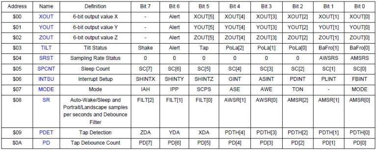
NOTE: The device must be placed in Standby Mode to change the value of the registers.
Test Code
Import program
00001 /* Author: Edoardo De Marchi
00002  * Name: Test Code for MMA7660FC
00003  */
00004 #include "mbed.h"
00005 #include "MMA7660FC.h"
00006
00007 #define ADDR_MMA7660 0x98                   // I2C SLAVE ADDR MMA7660FC
00008
00009 MMA7660FC Acc(p28, p27, ADDR_MMA7660);      //sda, scl, Addr
00010 Serial pc(USBTX, USBRX);
00011
00012
00013 float G_VALUE[64] = {0, 0.047, 0.094, 0.141, 0.188, 0.234, 0.281, 0.328, 0.375, 0.422, 0.469, 0.516, 0.563, 0.609, 0.656, 0.703, 0.750, 0.797, 0.844, 0.891, 0.938, 0.984, 1.031, 1.078, 1.125, 1.172, 1.219, 1.266, 1.313, 1.359, 1.406, 1.453, -1.500, -1.453, -1.406, -1.359, -1.313, -1.266, -1.219, -1.172, -1.125, -1.078, -1.031, -0.984, -0.938, -0.891, -0.844, -0.797, -0.750, -0.703, -0.656, -0.609, -0.563, -0.516, -0.469, -0.422, -0.375, -0.328, -0.281, -0.234, -0.188, -0.141, -0.094, -0.047};
00014
00015
00016
00017 int main()
00018 {
00019
00020     Acc.init();                                                     // Initialization
00021     pc.printf("Value reg 0x06: %#x\n", Acc.read_reg(0x06));         // Test the correct value of the register 0x06
00022     pc.printf("Value reg 0x08: %#x\n", Acc.read_reg(0x08));         // Test the correct value of the register 0x08
00023     pc.printf("Value reg 0x07: %#x\n\r", Acc.read_reg(0x07));       // Test the correct value of the register 0x07
00024
00025     while(1)
00026     {
00027         float x=0, y=0, z=0;
00028
00029         Acc.read_Tilt(&x, &y, &z);                                  // Read the acceleration
00030         pc.printf("Tilt x: %2.2f degree \n", x);                    // Print the tilt orientation of the X axis
00031         pc.printf("Tilt y: %2.2f degree \n", y);                    // Print the tilt orientation of the Y axis
00032         pc.printf("Tilt z: %2.2f degree \n", z);                    // Print the tilt orientation of the Z axis
00033
00034         wait_ms(100);
00035
00036         pc.printf("x: %1.3f g \n", G_VALUE[Acc.read_x()]);          // Print the X axis acceleration
00037         pc.printf("y: %1.3f g \n", G_VALUE[Acc.read_y()]);          // Print the Y axis acceleration
00038         pc.printf("z: %1.3f g \n", G_VALUE[Acc.read_z()]);          // Print the Z axis acceleration
00039         pc.printf("\n");
00040         wait(5);
00041
00042     }
00043 }
00044
The g values or tilt values are converted using the "MM7660FC ACQUISITION CODE TABLE" that you can find it on page 28 of the MMA7660FC datasheet.
Library
Import library
Public Member Functions |
|
| MMA7660FC (PinName sda, PinName scl, int addr) | |
|
Creates an
MMA7660FC
object connected to the specified I2C object.
|
|
| ~MMA7660FC () | |
|
Destroys an
MMA7660FC
object.
|
|
| void | init () |
|
Initialization of device
MMA7660FC
(required)
|
|
| void | read_Tilt (float *x, float *y, float *z) |
|
Read the Tilt Angle using Three Axis.
|
|
| int | read_x () |
|
Reads the x register of the
MMA7660FC
.
|
|
| int | read_y () |
|
Reads the y register of the
MMA7660FC
.
|
|
| int | read_z () |
|
Reads the z register of the
MMA7660FC
.
|
|
| char const * | read_Side () |
|
Reads the Front or Back position of the device.
|
|
| char const * | read_Orientation () |
|
Reads the Orientation of the device.
|
|
| char | read_reg (char addr) |
|
Reads from specified
MMA7660FC
register.
|
|
| void | write_reg (char addr, char data) |
|
Writes to specified
MMA7660FC
register.
|
|
| int | check () |
|
Checks if the address exist on an I2C bus.
|
|
The initialization is needed because it sets the "Mode" register to "Active Mode" which is required for read the data of the x,y,z axis.
Output
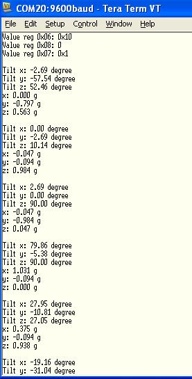
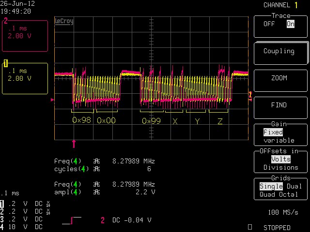
The image below show the data sent from I2C bus (clock = yellow signal, data = purple signal).
THANKS: thanks mbed and seeedstudio for the module
2 comments on Grove - 3 axis Accelerometer:
Please log in to post comments.

Thank you for your post. However you haven't post how to calculate the angle from the outputs. Please give me more details about that. THANKS