AVR910: In-System Programming using mbed
This notebook page details the implementation of the AVR910 In-System Programming protocol as specified in the AVR910 application note.
How it works
The AVR910 protocol uses a six pin connection which consists of a 3-wire SPI interface, a reset line, VCC and GND. All of these can be directly connected to the mbed. To initiate programming, the reset line must be pulled low, after which commands [specified in the AVR910 application note and AVR microcontroller datasheets] can be sent to the device being programmed.
The programmer first issues an enable programming command, reads the signature bytes of the device, then takes a raw binary file [.bin specified by the PATH_TO_BINARY definition in AVR910.h] and loads it byte by byte into the AVR microcontroller's page buffer which is written to flash memory whenever it is full.
At the end, flash memory is read byte by byte and compared to the binary file to check whether programming was successful or not.
Program
You can find the code for the programmer here:
It should be noted that the current implementation assumes the AVR microcontroller has paged flash memory.
Code
/**
 * Program an AVR with an mbed.
 */

// ATMega328 Datasheet:
//
//  http://www.atmel.com/dyn/resources/prod_documents/doc8271.pdf

#include "AVR910.h"

LocalFileSystem local("local");
Serial pc(USBTX, USBRX);

AVR910 mbedISP(p5, p6, p7, p8); //mosi, miso, sclk, nreset.

int main() {

    int success = -1;

    FILE *fp = fopen(PATH_TO_BINARY, "rb");

    if(fp == NULL){
        pc.printf("Failed to open binary. Please check the file path\n");
    }
    else{
        pc.printf("Binary file opened successfully\n");
        success = mbedISP.program(fp);
        fclose(fp);
    }

    if(success < 0){
        printf("Programming failed.\n");
    }
    else{
        printf("Programming was successful!\n");
    }

}
To do
- Support AVR chips which don't use paged memory
- Introduce a verbose and quiet mode to tidy up debugging statements
- Check command responses for synchronization errors during programming
- Anything else I've forgotten!
Example
I used the programmer to put this Attitude Heading Reference System (AHRS) onto the SparkFun 9DOF Razor IMU, which contains an ATMega328P.
After compiling the code with arduino-0018, I used hex2bin to convert the resulting .hex output to a raw binary which was then downloaded onto the chip using the programmer.
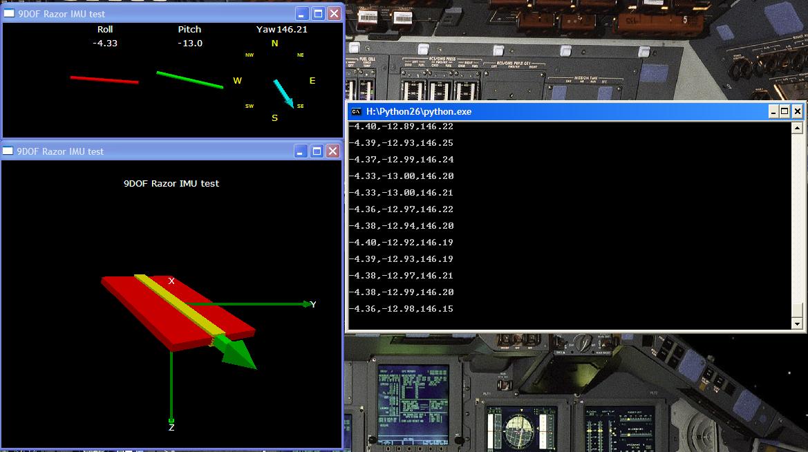
The AHRS program spits out heading data over a 2-wire serial interface - a nice way of visualising it is the python graphic interface via an FTDI USB-Serial cable:

However, as I needed the raw data on the mbed, I simply used a Serial object and parsed out the roll, pitch and yaw values:
#include "mbed.h"

Serial pc(USBTX, USBRX);
Serial razor(p9, p10);

float roll;
float pitch;
float yaw;

int main() {

    razor.baud(57600);

    while(1) {
        //Make sure we get to the start of a line.
        while(razor.getc() != '\n');

        razor.scanf("!ANG:%f,%f,%f\n", &roll, &pitch, &yaw);

        pc.printf("%f,%f,%f\n", roll, pitch, yaw);
    }

}
Now the data is available for any application I desire!
3 comments
You need to log in to post a comment

very coll, I was a little worried that I might be forced to only use the bootloader for the Razor IMU. Now I can program it using the mbed. Many thanks for uploading this. Could you let us know what should we look for in the Atmel data sheet to figure out if a given microcontroller is programmable via this method.