X10 Interface Server
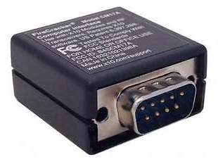
X10 is a popular technology for low cost home automation. This project is an X10 Server which uses an mbed module connected to an X10 CM17a module. This device is conveniently located on your network, after which it listens for commands that should be translated and forwarded to the CM17a module.
The CM17a module is an RF transmitter, so it sends the commands to an X10 compatible receiver (such as the TM751). The TM751 can turn on and off a directly connected device, and it can also "forward" the command to other modules attached to your AC power line.
 |  |
Features
This application is not a demo of the X10 interface. This is a full-featured "IOT" application that required no maintenance for the last 3 years. Here's the features in this SW -
- X10 Server to accept commands from the network and send them via a CM17a.
- Robust Ethernet Interface that handles connect and disconnect gracefully.
- Configuration settings are hosted in a .ini file on the mbed local file system.
- Automatic Software Update from a defined web server (checks once a day or on restart).
- Sets the RTC from an NTP server (doesn't really use this except as the clock for the software update).
- Command shell allows user interaction - send commands, update the software, set the clock.
- Watchdog running, should something go wrong it will try to bring it back.
2019 Update
On my wish list is the desire to make things on my network more discoverable. This was the motivation for an update.
- Added SSDP for device discovery. In Windows Explorer, this device now shows up in "Network".
- Clicking on this device in Windows Explorer brings up its web page.
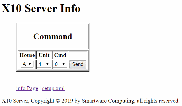
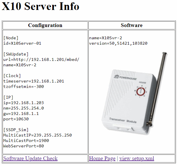
- Web page provides access to some details about the current running version.
- Web page permits forcing an early query for a software update (great for armchair deployment).
- Web page permits directly access to send a command (great for testing).
- Updated all "my" libraries to the latest version.
Import programX10Svr
X10 Server - IOT device to leverage a collection of old X10 devices for home automation and lighting control.
System Architecture
In ASCII art, here is the basic architecture of an installation of the overall system, of which the components of interest are the "X10 Server" connected to a CM17a module, which transmits commands to, and via, the TM751 module.
///  +---------+           +---------+           +=========+           +---------+
///  | Web     |- Internet-| Web     |- Network -| X10     |           | CM17a   |
///  | Browser |-\         | Server  |       |   | Server  |-- RS232 --| Module  |
///  +---------+  \        +---------+      /    +=========+           +---------+
///                \--- Intranet ----------/                                   /
///                                                                           /_
///                                                                            /
///    ~|+|~~~~~~~ AC Line ~~~|+|~~~~~~~~~~~~~~~~~~~|+|~~~~~~~~~~~~~~~~|+|~   /_
///    ~|+|~~~~~~~~~~~~~~~~~~~|+|~~~~~~~~~~~~~~~~~~~|+|~~~~~~~~~~~~~~~~|+|~    /
///      |                     |                     |                  |     /
///  +---------+           +---------+           +---------+           +---------+
///  | X10     |           | X10     |           | X10     |           | TM751   |
///  | Module  |           | Module  |           | Module  |           | Module  |
///  +---------+           +---------+           +---------+           +---------+
///      |                     |                     |                  |
///  +---------+           +---------+           +---------+           +---------+
///  |Appliance|           |Appliance|           |Appliance|           |Appliance|
///  |         |           |         |           |         |           |         |
///  +---------+           +---------+           +---------+           +---------+
X10 Server Components
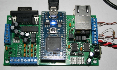
This version of the server has 3 basic components:
- The LPC1768 mbed supporting:
- Ethernet
- Local FileSystem
- A SmartBoard Baseboard (under the mbed). Features used on this baseboard:
- Ethernet
- The CM17a module (on the right), with one modification as detailed below.
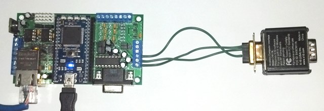
LPC1768 mbed module
The mbed module I don't need to say more about.
Smartboard Baseboard
The Baseboard I used is of my own design, and is way overkill for this project. I think many other baseboards would likely work as well. What's required? Ethernet, and 2 DigitalOut pins. You may notice that the Baseboard has an RS-232 port as well, but this was not used. There are two reasons - 1) the signals used by the CM17a are not connected on this baseboard, and 2) I may build another baseboard with the bare minimum components, and these parts would not be needed.
The photo above shows the Ethernet cable, and the USB cable. The USB cable is providing power to the module, and it is providing status information to the PC via USB serial. When this is "installed" elsewhere in the house, I can either use the USB as a power source (from a wall-wart supply), or 2 of the screw terminal pins can provide power to the module (also from a wall-wart), but with the on-board switching supply regulator, there is a bit more flexibility for input voltage (7 to 30v).
Onboard Web Server
I implemented a small web server on the mbed module. This web server provides primary a handy interface to prove it is online, and secondarily, a means to test and force software update checks.
 |  |
External [Web] Server
The Web Server I use with this is only 1 of the possible sources of command. But this UI makes a simple front-end that is accessible from anywhere, and it is designed to scale well to smart phones. Running on a secure server means that not just anybody can control the exposed systems.
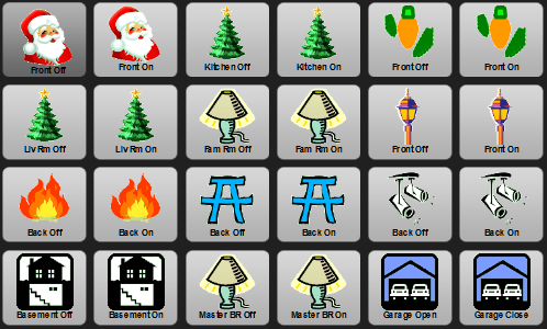 | Shown here is the Christmas theme. |
Network Transaction
But what actually crosses the network to this X10 Server? A simple text string with one or more commands in it.
PHP function to send a message
/// SendCommandMessage
///
///	Construct and send the X10 packet.
///
/// @param $packet is the message to send
/// @return true if it thinks it sent the packet successfully
/// @return false if it thinks something went wrong and it could not send
///
function SendCommandMessage($packet)
	{
	global $X10ServerIP, $X10ServerPort, $X10ServerTimeout;

	$sock = @fsockopen('tcp://'.$X10ServerIP, $X10ServerPort, $errno, $errstr, $X10ServerTimeout);
	if (!$sock)
		{
		return false;
		}
	fwrite($sock, $packet);
	fclose($sock);
	return true;
	}
There are a few global settings as you can see. Everything is configurable in another file, but here is an example configuration:
Configuration Settings
$X10ServerIP = "192.168.1.225";  // Alternately, this could be "X10Server-01", if the Ethernet stack supports hostname.
$X10ServerPort = 10630;
Command Set
If you are familiar with X10, you know that there are 16 "House" codes and 16 "Unit" codes. In X10 terminology, the house codes are identified by letters "a" through "p" and the unit codes by the numbers 1 through 16.
Also, you can send an on, off, brighten or dim command. On and Off are designated with "1" and "0". To brighten or dim a lamp module, there are a maximum of 6 steps, so the command is either a '+' or '-' and a number from 1 to 6.
Each piece is separated by a space, and you can cascade several commands in one. Using the PHP API above -
Send X10 Command
SendCommandMessage("a1 1 a2 0 a4 +3 j16 -2 p2 0");
CM17a module
The CM17a module is one of many X10 compatible components. While this module is not for sale new, they seem to be plentiful through other sources, such as ebay.
Information
The CM17a module is designed to plug on to an RS-232 port on a PC. The RS-232 standard uses voltages that range from about -3 (to -12) as a "mark" and +3 (to +12) as a "space". Modern PCs tend to use technology that ranges from -5 (or even 0v) to perhaps only +5v. The CM17a module diode or's two of these signals to extract power and each independently to extract signal, all from the RS-232 port. You'll see later that both pins do not go to zero during a data transfer. If they did, the CM17a would lose power. These diodes drop the input voltage about 0.6v. The mbed uses 0 to 3.3v on its port pins, and 3.3v minus 0.6v doesn't leave much for the CM17a module. In fact, it didn't send any messages even though I could see a signal. More on this later, including instructions for a small modification.
CM17a Modification
The CM17a draws its power and gets its messages from the mbed port pins to which it is wired. The CM17a is a very low power device, so this is not a problem.
 | What is a problem is that the CM17a module didn't work when connected to the 3.3v port pins. It prefers a higher voltage. I opened it up to see if I could "fix" it. |
If you gently pry the case away from the DB-9 connectors, it may pop open without breaking anything (as mine did). Then, gently lift out the connector and the PCB, which is simply attached by wires.
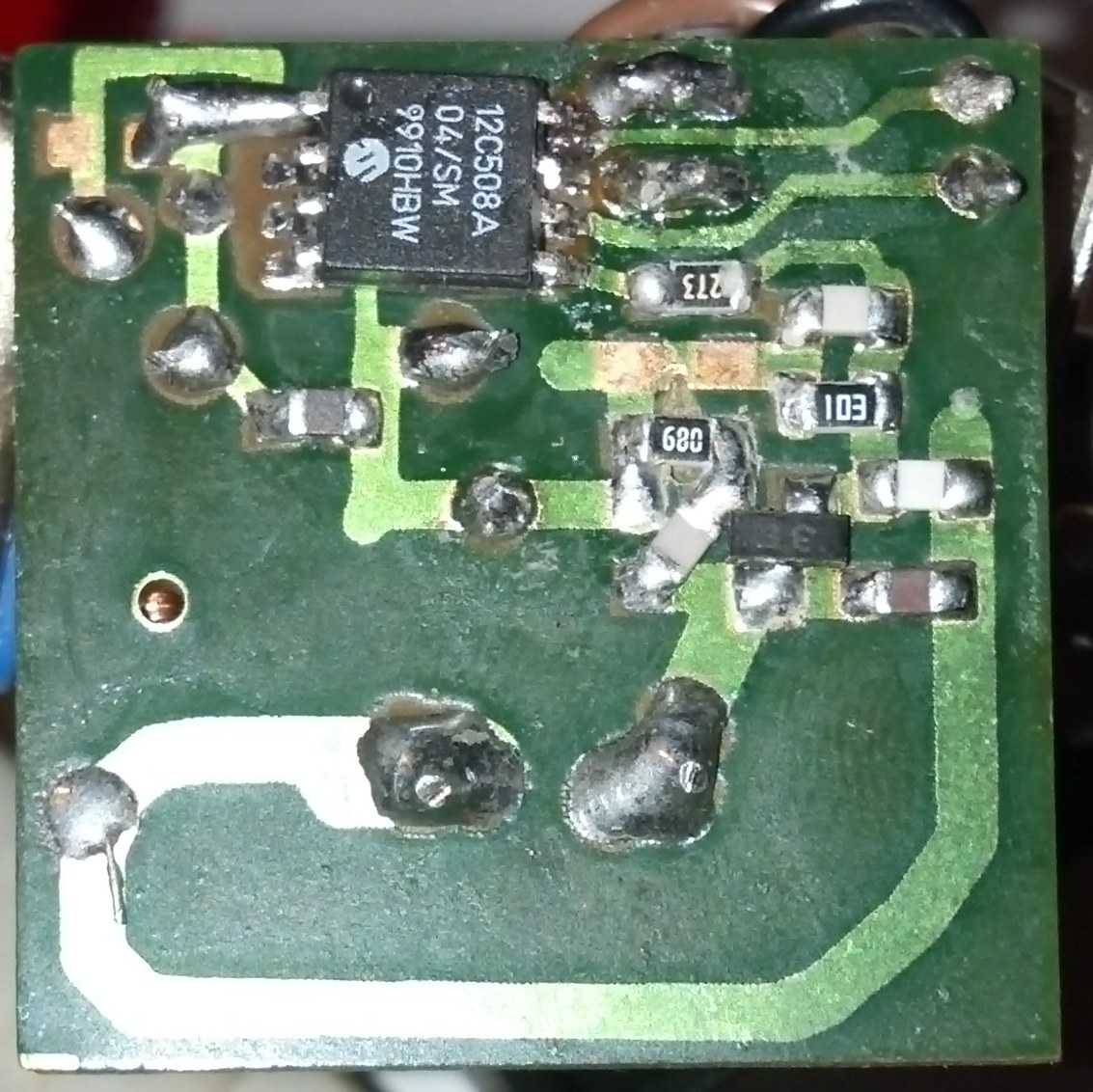
The 8-pin part at the top is a Microchip microcontroller - the PIC12C508. In looking at the 8-pin IC at the top, the small dimple in the top-left corner indicates pin 1. Going counter-clockwise, pins 2, 3, and 4 are down the left side, and pins 5, 6, 7, and 8 go up the right hand side. This micro has an internal 4 MHz oscillator, and 6 IO pins in an 8-pin package. It also has a whopping 3/4 K of Program, and 25 Bytes of RAM. I'm guessing the code in there is pure-assembly language.
I probed the circuit for signals with my digital scope, and I found what I was looking for. Pins 5 and 6 are where the signals come in from the DB-9. In ASCII art, the signals look like this:
    ///
    ///        GND   DTR   TxD   RxD   DCD       DB-9 Standard Pinout
    ///         5     4     3     2     1        used by CM17a module
    ///            9     8     7     6
    ///           RI    CTS   RTS   DSR
    ///
    /// DB-9    LowPower | Standby    | '1' | Wait | '0' | Wait | '1' | Wait...
    ///                   ___  _______       ___________________       ________
    /// DTR(4)  _________|   //       |_____|                   |_____|
    ///                   ___  ____________________       _____________________
    /// RTS(7)  _________|   //                    |_____|
    ///
    ///                               | bit period | = 1/BaudRate
    /// GND(5)
And, here's a few scope traces:
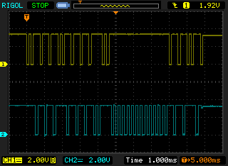 | Sending the command A1 1. |
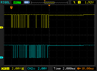 | Sending the command A1 0. |
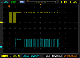 | Sending the command A1 0, showing one of the data lines and then the signal feeding the RF transmitter. |
After this micro receives the X10 command from the mbed module, it generates the signal on Pin 5 for the RF transmitter. The transmitter is a pretty simple circuit - this signal first hits the transistor (right side about midway down), where it is amplified and sent to a tuned LC oscillator (the inductor is on the other side of the PCB).
As I probed the signal from the micro to the transistor, it seemed clear that there simply wasn't enough of a drive signal being generated.
How to boost the signal -
- Increase the voltage to this module.
- Increase the drive signal to the transmitter.
I went with the 2nd option. Connected to pin 5 is a 27K ohm resistor ("273" is on the label as you see in the picture above). I wanted to lower the value of this resistor, to increase the drive current to the transistor. I scavenged my junk box and came across a 15K resistor. First I just held it in place over top of the 27K resistor with my finger, and the messages were getting out. So, I soldered it down. 27K in parallel with 15K is about 9.6K.
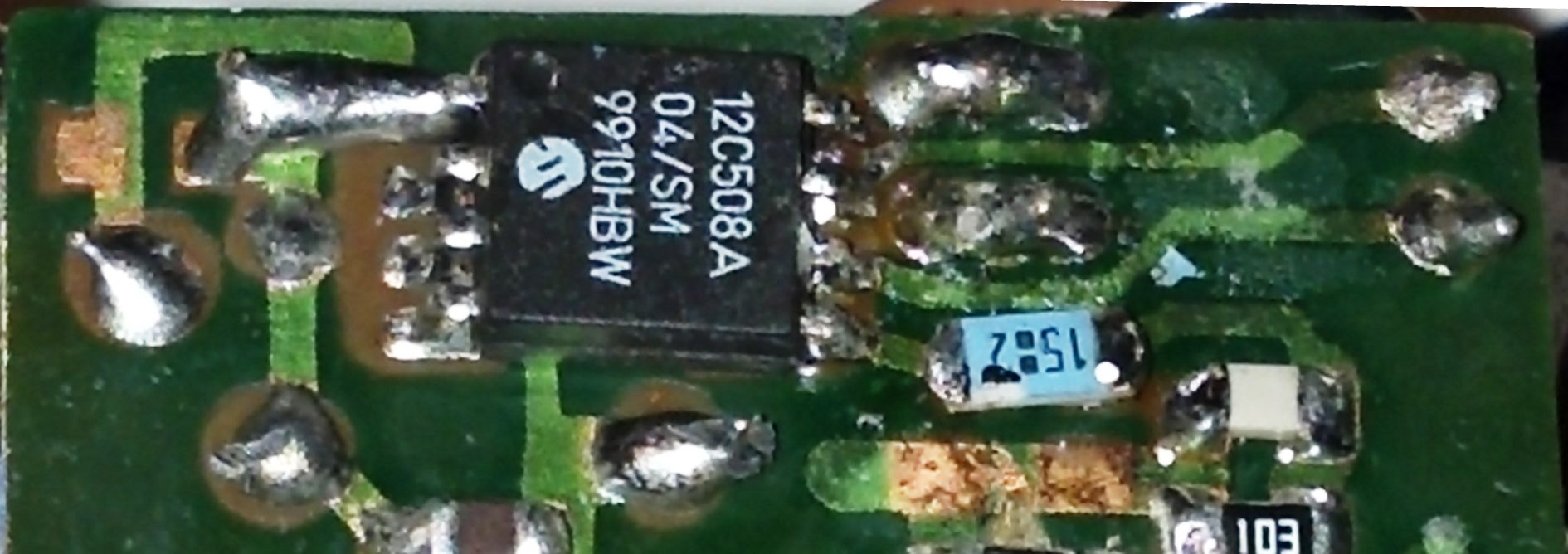
You can see the new part in the same location. It is a larger part, but it worked by just tacking it down over the old part. The label on this part got a bit warm and smudged the number. I think this was a 15.8K, so the label "1582" translates to 15800 ohm. I suspect anything from 5K to 20-some K would have also worked. I could have used a leaded resistor, but it probably wouldn't fit back into its case when I was done.
I would have like to try option 1 - increase the voltage to this module, by replacing the two diodes with Schottky diodes. That would have changed the voltage drop from 0.6V to 0.3V, which might also have boosted the signal enough - but I didn't have any of those in my junk box.
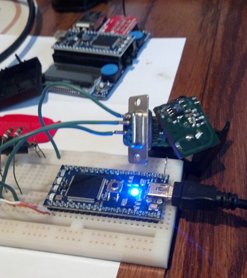
While working through the software and the hardware, here's a picture of the unit on the bench.
Summary
The main goal for this project was to replace a service on an "always on" PC with a small low-power embedded appliance. This goal has been fully met.
| ====================== | In reality, the PC in question had a few "always on" applications - the X10 server among them. With this project completed, I power-down that PC when not in-use as the lab system. This saves significant energy. |
This was a weekend project, which included all the research and the hardware work.
I've been working with the mbed for a few years now. It has been purely as a hobby so far. But over this time I've built several libraries, and derived my own version of many other libraries. This project involved "gluing" together different library files and creating two small libraries. Along the way I had to diagnose the communications signals, do a bit of online research, find a resistor in the junk-box and solder it in place. I already had the baseboard built and operational for some other work.
| Feature | Lines of Code | Description |
|---|---|---|
| X10 Driver | 400 | My new X10 Driver is kind of bloated. I think if I cleaned it up I'd knock 50 or more lines off of it without losing functionality. |
| X10 Server | 80 | Also a new part, the server parses the commands from the network side and makes them available to send to the X10 Driver. |
| main | 400 | All the start-up logic, the network connection, software update, watchdog, time sync, shell interface, and the glue to route from the X10 Server to the X10 Driver. |
| EthernetInterface | lots | My slightly customized version of the EthernetInterface originally provided with mbed OS 2 |
| HTTPClient | lots | My heavily customized version of HTTPClient by mbed |
| INIManager | 625 | My creation of an "ini-file" manager to read/write and manage configuration settings. |
| SSDP | 255 | My creation of an SSDP server, which makes itself visible to the network |
| SW_HTTPServer | 1140 | My creation of a rather capable web server, with CGI, SSI and more |
| SW_String | 200 | My creation of a few string functions that are not baked in to the standard libraries |
| SWUpdate | 300 | My creation of a SW Update feature, suitable only for those with a local file system |
| TimeInterface | 1200 | My creation of a time library, which includes NTP Sync and some calendar functions |
| Watchdog | 100 | My adaptation of a watchdog feature - adapted from mbed |
So, the sum of the lines of code is for the .cpp files only. But each library has a comprehensive header file with detailed documentation. And since most of the libraries are more general purpose, they have been used in many projects already.
External References
Please log in to post comments.
