A simple oscilloscope using Adafruit 2.8" TFT with touch. Runs on FRDM-KL25Z, FRDM-K22F, FRDM-K64F, NUCLEO-F411RE. 2 channel analog inputs with 4 trigger modes and time division.
Dependencies: SPI_STMPE610 UniGraphic mbed vt100
My first attempt of implementing an oscilloscope using FRDM-KL25Z and Adafruit 2.8" TFT with touch.
FRDM-KL25Z と Adafruit 2.8" TFT with touch を使用して作ってみた最初のオシロスコープです。
On 25-Sep-2017, wrong calculation of trigger pos/val fixed.
On 25-Nov-2015, FRDM-K64F and NUCLEO-F411RE platforms were added.
On 26-Nov-2015, FRDM-K22F is added (tested).
Note: Now ch2 is A2 instead of A1!
25-Sep-2017, トリガー値と位置の計算の誤りを修正しました。
25-Nov-2015, FRDM-K64F と NUCLEO-F411RE でも動くようになりました。
26-Nov-2015, FRDM-K22F でも動作確認が出来ました。
※一身上の都合で、アナログ入力の ch2 は A1 から A2 に変更しましたので、ご注意ください。m(_ _)m
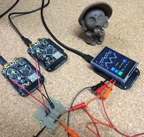
This supports two analog inputs A0 for channel 1 and A2 for channel 2
and four trigger modes (NONE, RISE, FALL, LEVEL),
time division is 30us to 20ms per pixel which will make 300us/div to 200.0ms/div (as 10 pixels per div)
A0と A2 のアナログ2入力にて、
4種類のトリガーモード(NONE: フリーラン RISE: 立ち上がりエッジ、FALL: 立下りエッジ、LEVEL: レベル) 。
サンプリングは30us から 20ms, チャートの1メモリが10ピクセルなので、300us/dev から 200.0ms/div となっています。
The analog signals and gnd was picked at the pins in the picture above.
Note: now you need to pick A0 and A2 instead of A0 and A1.
信号は上記の写真のように、Adafruit のピンからつまみました。
変更により、A0とA2が入力となります。
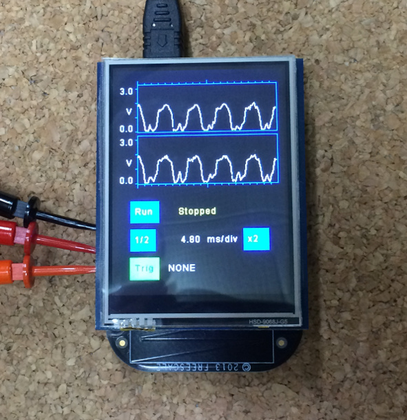
When powered on or reset, the program starts in Trigger Mode = NONE (Free Run Mode)
電源投入、リセット後 プログラムはトリガーモード NONE (フリーランモード) で起動します。
To change trigger mode and/or time division, press run/stop button.
トリガーモードを変えたり、サンプリング時間を変えるのには run/stop ボタンを押してください。
Each time you push Trig button, the trigger mode changes
NONE -> RISE -> FALL -> LEVEL ( -> NONE).
トリガーボタンを押すたびにトリガーモードは
NONE(フリーラン) -> RISE (立ち上がりエッジ) -> FALL (立下りエッジ) -> LEVEL (レベル)
と変化します。
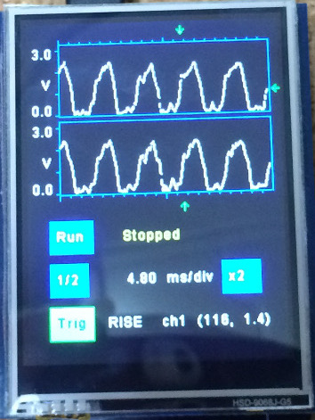
When trigger mode is not NONE,
to specify the trigger position, level and channel, push inside the wave frame.
Then green trigger marks will be shown and value of trigger position and voltage will be printed.
トリガーモードが NONE でないときに、チャネルの枠内をタッチしますと、
その位置がトリガーのポジション、レベル、チャネルになります。
そして、緑色のトリガーマークが表示され、下部にはトリガーの具体的なポジションとボルテージが表示されます。
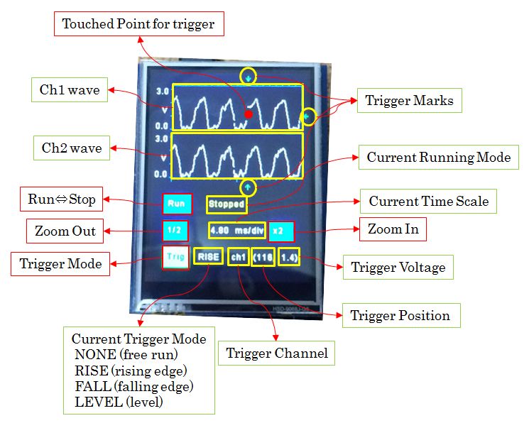
To change time division push
"1/2" to Zoom Out (sampling interval will be bigger) or
"x2" to Zoom In (Sampling interval will be smaller).
サンプリングタイムを変更するのには
"1/2" ズームアウト (サンプリング間隔が長くなります) か
"x2" ズームイン (サンプリング間隔が短くなります。) を押してください。
On 7-Mar-2015 updated to UniGraphic library version!
2015年3月7日 UniGraphic ライブラリ使用版にアップデートしました。
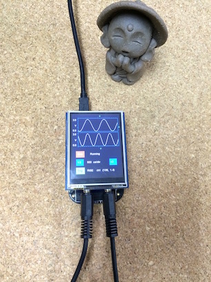 FRDM-KL25Z
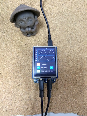 FRDM-K64F
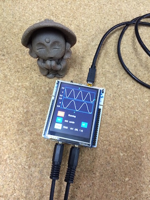 NUCLEO-F411RE
Diff: main.h
- Revision:
- 6:c93e2f12b789
- Parent:
- 4:6f3532a1a962
- Child:
- 8:62982cc8e5d8
--- a/main.h	Wed Nov 25 12:56:02 2015 +0000
+++ b/main.h	Wed Nov 25 13:07:28 2015 +0000
@@ -10,59 +10,96 @@
  * THE SOFTWARE.
  */
 #ifndef _MAIN_H_
-#define _MAIN_H_ inluded
-
-// uncomment following line if K64F rev is E or later
-#define FRDM_K64F_VE
+#define _MAIN_H_ included

-#if   defined (TARGET_KL25Z)
+#if defined (TARGET_KL25Z)
+#define PIN_SCLK        PTD1
+#define PIN_MISO        PTD3
 #define PIN_MOSI        PTD2
-#define PIN_MISO        PTD3
-#define PIN_SCLK        PTD1
 #define PIN_CS_TFT      PTD0
 #define PIN_DC_TFT      PTD5
+#define PIN_CS_TSC      PTA13
 #define PIN_BL_TFT      PTC9
 #define PIN_CS_SD       PTA4
-#define PIN_CS_TSC      PTA13
-#define PIN_TSC_INTR    PTC9
-#define PIN_RESET_TFT   PTB10
+#define PIN_TSC_INTR    PTC9 /* place holder */
+#define PIN_RESET_TFT   PTB10 /* place holder */
 #define PIN_ADC_CH0     PTB0
-#define PIN_ADC_CH1     PTB1
+#define PIN_ADC_CH1     PTB2

 #elif defined (TARGET_KL46Z)
-#define PIN_MOSI        PTD6
+#define PIN_SCLK        PTD5
 #define PIN_MISO        PTD7
-#define PIN_SCLK        PTD5
+#define PIN_MOSI        PTD6
 #define PIN_CS_TFT      PTD4
 #define PIN_DC_TFT      PTD2
+#define PIN_CS_TSC      PTA13
 #define PIN_BL_TFT      PTC9
 #define PIN_CS_SD       PTA4
-#define PIN_CS_TSC      PTA13
-#define PIN_TSC_INTR    PTC9
-#define PIN_RESET_TFT   PTA20
+#define PIN_TSC_INTR    PTC7 /* place holder */
+#define PIN_RESET_TFT   PTC6 /* place holder */
 #define PIN_ADC_CH0     PTB0
-#define PIN_ADC_CH1     PTB1
+#define PIN_ADC_CH1     PTB2

 #elif defined (TARGET_K64F)
-#define PIN_MOSI        PTD2
+#define PIN_SCLK        PTD1
 #define PIN_MISO        PTD3
-#define PIN_SCLK        PTD1
+#define PIN_MOSI        PTD2
 #define PIN_CS_TFT      PTD0
 #define PIN_DC_TFT      PTC4
+// for board rev E or later
+#define PIN_CS_TSC      PTC12
+// for earlier boards use following line
+// #define PIN_CS_TSC      PTA0
 #define PIN_BL_TFT      PTC3
 #define PIN_CS_SD       PTB23
-#ifdef FRDM_K64F_VE
-#define PIN_CS_TSC      PTC12
-#else
-#define PIN_CS_TSC      PTA0
-#endif
-#define PIN_TSC_INTR    PTC3
-#define PIN_RESET_TFT   PTB20
+#define PIN_TSC_INTR    PTC0 /* place holder */
+#define PIN_RESET_TFT   PTC9 /* place holder */
 #define PIN_ADC_CH0     PTB2
-#define PIN_ADC_CH1     PTB3
+#define PIN_ADC_CH1     PTB10
+
+#elif defined (TARGET_K22F)
+#define PIN_SCLK        PTD5
+#define PIN_MISO        PTD7
+#define PIN_MOSI        PTD6
+#define PIN_CS_TFT      PTD4
+#define PIN_DC_TFT      PTA1
+#define PIN_CS_TSC      PTB19
+#define PIN_BL_TFT      PTC6
+#define PIN_CS_SD       PTA4
+#define PIN_TSC_INTR    PTC7 /* place holder */
+#define PIN_RESET_TFT   PTC9 /* place holder */
+#define PIN_ADC_CH0     PTB0
+#define PIN_ADC_CH1     PTC1
+
+#elif defined (TARGET_NUCLEO_F411RE)
+#define PIN_SCLK        PA_5
+#define PIN_MISO        PA_6
+#define PIN_MOSI        PA_7
+#define PIN_CS_TFT      PB_6
+#define PIN_DC_TFT      PC_7
+#define PIN_CS_TSC      PA_9
+#define PIN_BL_TFT      PA_8
+#define PIN_CS_SD       PB_5
+#define PIN_TSC_INTR    PA_8 /* place holder */
+#define PIN_RESET_TFT   PA_13 /* place holder */
+#define PIN_ADC_CH0     PA_0
+#define PIN_ADC_CH1     PA_4

 #else
-  #error TARGET NOT DEFINED
+ #error TARGET NOT DEFINED
+#define PIN_SCLK        D13
+#define PIN_MISO        D12
+#define PIN_MOSI        D11
+#define PIN_CS_TFT      D10
+#define PIN_DC_TFT      D9
+#define PIN_CS_TSC      D8
+#define PIN_BL_TFT      D7
+#define PIN_CS_SD       D4
+#define PIN_TSC_INTR    D5-inside /* place holder */
+#define PIN_RESET_TFT   D4-inside /* place holder */
+#define PIN_ADC_CH0     A0
+#define PIN_ADC_CH1     A2
+
 #endif

 #define CHART_LEN    198