Gesture Arm Robot
Description
The purpose of this project is to control a robotic arm through only gesture controls. This is mostly a proof-of-concept to see how far the idea can go. Overall, while the arm does respond to the way the hand moves, using trilateration and inverse kinematics alone may be to much for the sensor to handle, and if future work is done, may require the addition of swiping motion and a sort of feedback control to better stabilize the robot arm.
Components
- mbed (LPC1768)
- SI1143 Gesture Sensor
- SparkFun Robotic Arm
- 4 servo motors
- 2 Hitec HS-322HD
- 1 DGServo S06NF STD
- 1 Hitec HS-85BB+
- 4 AA batteries
- Hitachi HD44780 LCD
- Some sort of base
- Header wires
Libraries
This is my own library needed to control the gesture sensor.
Import librarySI1143
Starting library to get the SI1143 Gesture Sensor to work. Currently only works in forced conversion mode.
This is the most common LCD library, used mainly for debugging and outputting certain data.
Import libraryTextLCD
TextLCD library for controlling various LCD panels based on the HD44780 4-bit interface
Setup
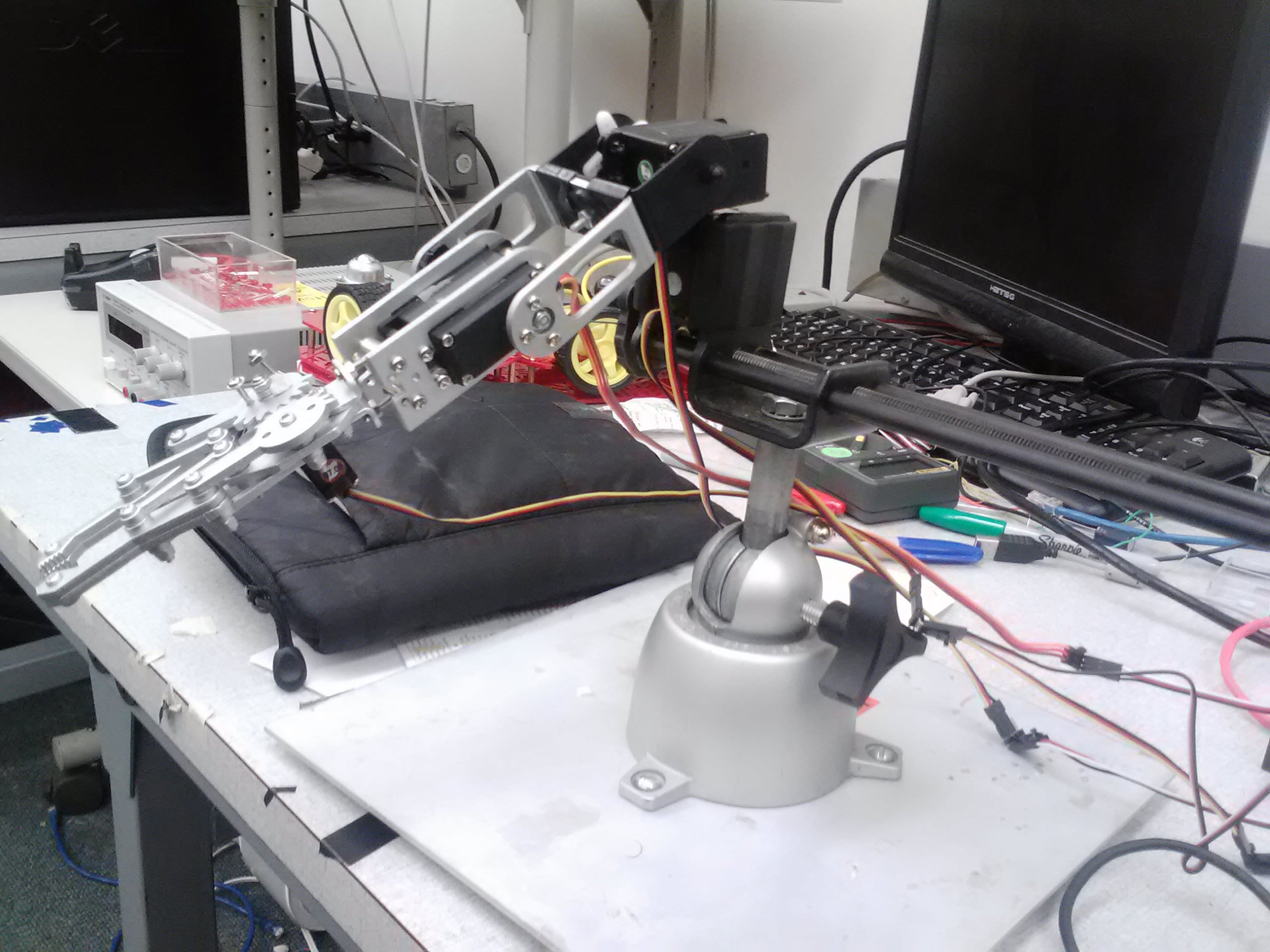
Setting up the parts is simple enough. Place the robot arm on the chosen base and make sure it is held tight. Starting at the base of the arm and beginning at the start of the servo list, the first servo is the spin servo, the second is the shoulder servo, the third is the elbow servo, and the fourth is the gripper servo. The LCD is used to display debugging information such the angles for the first three servos and the x, y, and z position of your hand.
Basic LCD Hookup
| Pin number | TextLCD pins | mbed pins |
|---|---|---|
| 1 | GND | 0V |
| 2 | VCC | 3.3V, though 5V is valid |
| 3 | VO | 0V, via 1k resistor |
| 4 | RS | p15 |
| 5 | RW | 0V |
| 6 | E | p16 |
| 7 | D0 | not connected |
| 8 | D1 | not connected |
| 9 | D2 | not connected |
| 10 | D3 | not connected |
| 11 | D4 | p17 |
| 12 | D5 | p18 |
| 13 | D6 | p19 |
| 14 | D7 | p20 |
The gesture sensor is controlled through I2C, make sure it placed somewhere on the board where there is little to no obstruction.
Basic Hookup
| SI1143 pins | mbed pins |
|---|---|
| GND | 0V |
| VIN | 3.3V |
| INT | not connected |
| SCL | p27, via 4.7k resistor to VIN |
| SDA | p28, via 4.7k resistor to VIN |
To hookup the arm, make sure there are at least four PwmOut pins available (P21-P26). Use header wires to extend the distance between the arm and the mbed. The servos need their own power source, as the servos initial startup will short the mbed. Make sure that you ground the separate power to the same source used by the mbed, else the servos will just spin in one direction. Each servo requires a signal, a Vin, and a ground, though the colors on the wires may vary between servos, see the second reference source if you are not sure which wire is which.
Theory
Trilateration
The first step is to get the 3 LED sensor measurements, which are based off the distance between the LED and the object. The value that is outputted from the sensor is arbitrary and becomes larger the closer the object, thus, a ratio formula must be applied to convert the value into cm and to decrease in value the further away the object is.
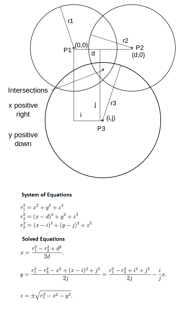
Afterward, 3D trilateration must be used to create x, y, and z values in a Cartesian coordinate space. Trilateration works by creating a sphere from one of the LEDs to the object, then another sphere from another LED to the object. These overlapping spheres creates a circle, and one final sphere created from the last LED creates two point of contact, in which the positive value is taken.
Spin Rotation
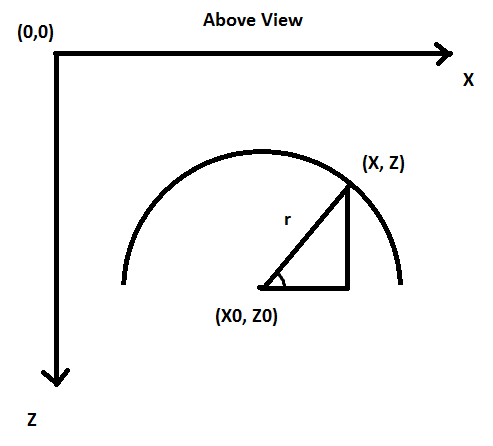
The second step is to get the angle for the spin servo. Looking from the top, an x-z plane can be imagined, where the arm base can be place. Trigonometry (arctangent) can then be used to solve the angle needed for the shoulder servo.
Inverse Kinematics
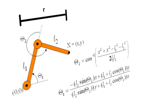
The final step involves inverse kinematics, since a determined point needs to be reached but the angles are unknown. Before starting, two things need to be done. One is to get the polar length of r from the previous section, allowing work to be done in a 2D space, Two is to adjust our arccosine numerator when it wraps around, to avoid non attainable numbers. Angle 2 is the elbow servo that is solved first, then angle 1 is the shoulder servo that is solved last. Note that in the code that the negative used to attain angle 1 was removed.
Pulse Conversion
Each servo type requires a specific pulsewidth in order to rotate to the appropriate angle. These are the values that were attained, where i is the angle ranging from 0 (max counter-clockwise position) to 180 (max clockwise position).
Conversion Chart
| Servo brand | Pulsewidth(us) |
|---|---|
| Hitec HS-322HD | 800 + (i*20)/3 |
| DGServo S06NF STD | 2300 - (i*95)/9 |
| Hitec HS-85BB+ | 600 + (i*10) |
Gripper Control
This servo works independently from the other servos, and instead uses the raw values from the sensor. By pushing forward and coming back with your hand, the gripper will either open or close. The code is programmed so that if the gripper is opened, LED1 on the mbed lights up.
Final Setup
Program Code
Import program
00001 #include "mbed.h"
00002 #include "SI1143.h"
00003 #include "TextLCD.h"
00004
00005 #define PI 3.14159265
00006
00007 DigitalOut led1(LED1);
00008 SI1143 sensor(p28, p27);
00009 PwmOut spin(p21);
00010 PwmOut shoulder(p22);
00011 PwmOut elbow(p25);
00012 PwmOut grip(p26);
00013 TextLCD lcd(p15, p16, p17, p23, p19, p24);
00014 Serial pc(USBTX, USBRX);
00015
00016 int main()
00017 {
00018     //LED sensor, bottom-left, top-left, bottom-right
00019     int s1,s2,s3;
00020     double sense1,sense2,sense3;
00021
00022     //distance between sensors in cm
00023     double diff = 5;
00024
00025     //sensed and stored coordinates
00026     double xs,ys,zs;
00027     double x=45,y=5,z=50;
00028
00029     //arbitrary position for arm
00030     double stx=60,sty=25,stz=100;
00031
00032     //length of arm segment
00033     double len12=7.5, len23=15;
00034
00035     //polar distance
00036     double r;
00037
00038     //check values
00039     double root, tproot, wproot;
00040     int timer=0;
00041
00042     //motor 1,2,3
00043     double angle_sp,angle_sh,angle_el;
00044
00045     //Setup
00046     lcd.cls();
00047     led1 = 0;
00048     grip.pulsewidth_us(700);
00049     sensor.bias(4,20);
00050     wait(1);
00051
00052     while(1)
00053     {
00054         //Read each led sensor
00055         s1 = sensor.get_ps1(4);
00056         s2 = sensor.get_ps2(4);
00057         s3 = sensor.get_ps3(4);
00058         sense1 = /*1000 - */1500/s1;
00059         sense2 = /*1000 - */1500/s2;
00060         sense3 = /*1000 - */1200/s3;
00061
00062         //Control for gripper
00063         if (((s1>800) || (s2>600) || (s3>600)) && !timer)
00064         {
00065             timer=20;
00066             if (!led1)
00067             {
00068                 led1 = 1;
00069                 grip.pulsewidth_us(1350);
00070             }
00071             else
00072             {
00073                 led1 = 0;
00074                 grip.pulsewidth_us(700);
00075             }
00076         }
00077         timer--;
00078         if (timer < 0) timer=0;
00079
00080         //Set outer limit
00081         if (sense1>110) sense1 = 110;
00082         if (sense2>110) sense2 = 110;
00083         if (sense3>110) sense3 = 110;
00084
00085         //Trilateration for x
00086         xs = 40 + ((pow(sense1,2) - pow(sense3,2) + pow(diff,2)) / (2*diff));
00087         if (xs<5) xs = 10;
00088         if (xs>95) xs = 90;
00089
00090         //Trilateration for y
00091         ys = -sty + ((pow(sense1,2) - pow(sense2,2) + pow(diff,2)) / (2*diff));
00092         if (ys<-50) ys = -40;
00093         if (ys>50) ys = 40;
00094
00095         //Trilateration for z
00096         root = pow(sense1+60,2) - pow(y,2) - pow(x,2);
00097         zs = sqrt(root);
00098         if (zs>70) zs = 70;
00099
00100         //Tolerance level to store x,y,z
00101         if (abs(x-xs) <= 7) x = xs;
00102         if (abs(y-ys) <= 10) y = ys;
00103         if (abs(z-zs) <= 6) z = zs;
00104
00105         //Used for debugging
00106         //x=60;
00107         //z=15;
00108         //for(y=-90;y<=90;y+=10){wait(1);
00109
00110         //Angle for spin motor, converted into degrees
00111         angle_sp = atan((stz - z)/(x - stx)) * 180/PI;
00112         if (angle_sp < 0)
00113             angle_sp += 180;
00114         angle_sp = 180 - angle_sp;
00115
00116         //Polar distance and arcosine wrapping
00117         r = sqrt(pow(x - stx,2) + pow(stz - z,2));
00118         wproot = 2*pow(r,2) - pow(len12,2) - pow(len23,2);
00119         while (wproot > 225)
00120             wproot -= 225;
00121         while (wproot < -225)
00122             wproot += 225;
00123
00124         //Angles for elbow motor first, then shoulder motor
00125         angle_el = acos(wproot/(2*len12*len23));
00126         tproot = len12 + len23*cos(angle_el);
00127         angle_sh = (-r*len23*sin(angle_el) + y*tproot)/(y*len23*sin(angle_el) + r*tproot);
00128
00129         //Angles for shoulder and elbow motor, converted into degrees
00130         angle_sh = 180 - (angle_sh * 180/PI);
00131         angle_el = 90 + (angle_el * 180/PI);
00132
00133         //Covert degrees to pulses to appropriate motors
00134         spin.pulsewidth_us(800 + (angle_sp*20)/3);
00135         shoulder.pulsewidth_us(800 + (angle_sh*20)/3);
00136         elbow.pulsewidth_us(2300 - (angle_el*95)/9);
00137
00138         //Debug info
00139         printf("%.1f %.1f %.1f\r\n",xs,ys,zs);
00140         //printf("%.1f %.1f %.1f\r\n",x,y,z);
00141         //printf("%d %d %d\r\n",s1,s2,s3);
00142         lcd.cls();
00143         lcd.printf("sp:%.0f sh:%.0f\nel:%.0f ",angle_sp,180-angle_sh,angle_el);
00144         lcd.printf("%.0f,%.0f,%.0f",x,y,z);//}
00145         //printf("%.2f %.2f %.2f\r\n\n",angle_sp,angle_sh,angle_el);
00146     }
00147 }
Robot Arm
mbed Platform
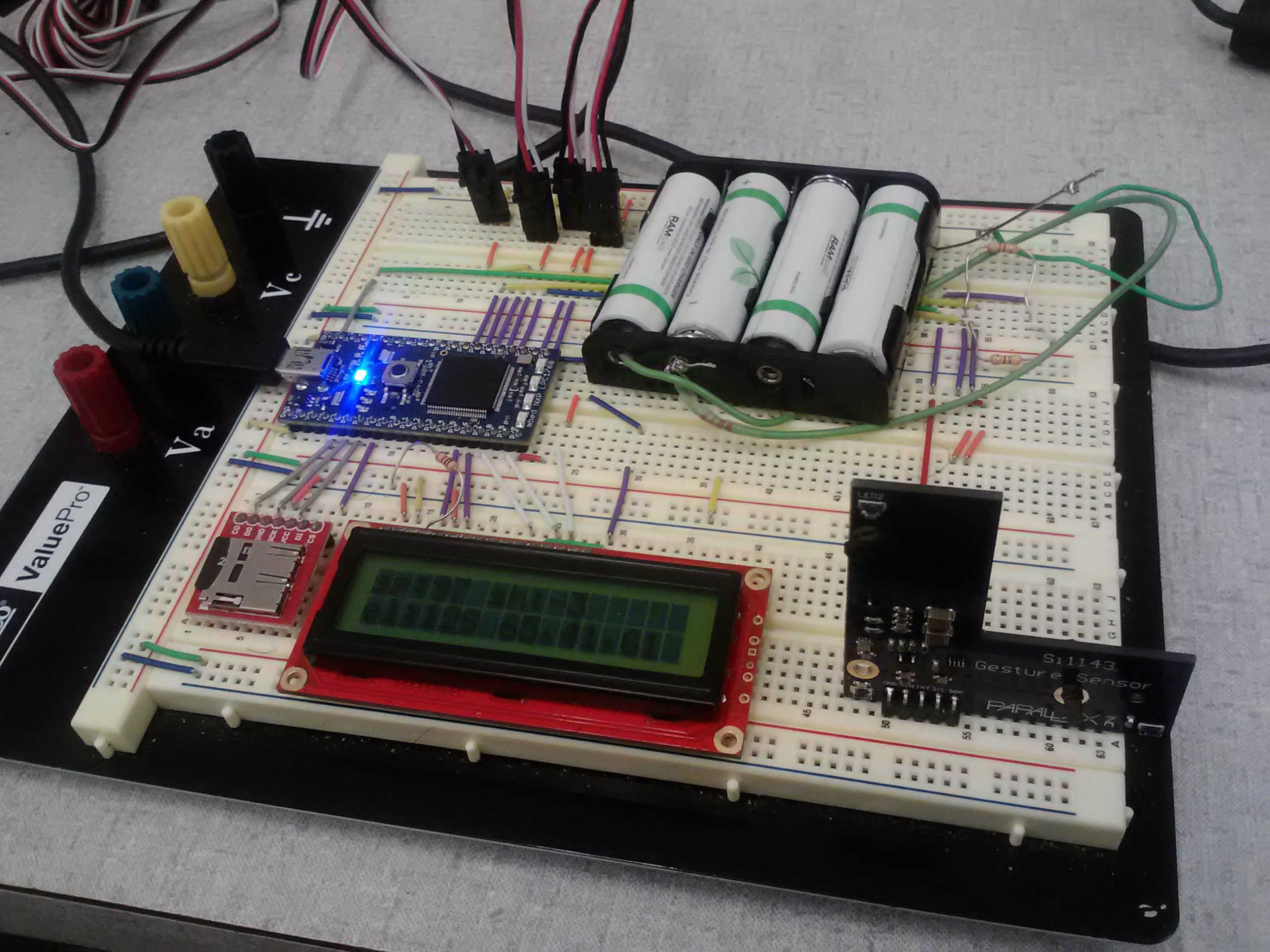
Note that the SD card is not used here.
Demo Video
References
- http://mbed.org/users/GAT27/notebook/si1143-gesture-sensor/
- http://www.horrorseek.com/home/halloween/wolfstone/Motors/svoint_RCServos.html#ServoConnectors
- http://en.wikipedia.org/wiki/Trilateration
- http://www.cs.princeton.edu/courses/archive/fall99/cs426/lectures/kinematics/sld008.htm
- http://en.wikipedia.org/wiki/Servo_control
Please log in to post comments.
