Important changes to repositories hosted on mbed.com
Mbed hosted mercurial repositories are deprecated and are due to be permanently deleted in July 2026.
To keep a copy of this software download the repository Zip archive or clone locally using Mercurial.
It is also possible to export all your personal repositories from the account settings page.
Dependencies: C12832_lcd EthernetInterface LM75B NTPClient SimpleSMTPClient TextLCD beep mbed-rtos mbed
Fork of RTOS_Project by
Homepage
Description:
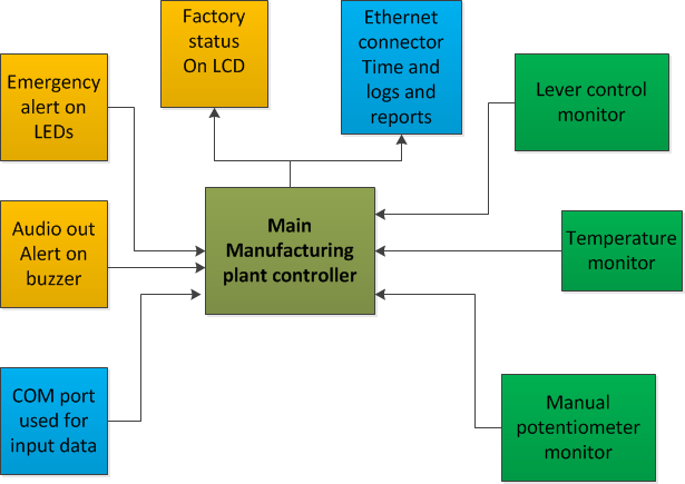
RTOS project : Connected and automated manufacturing plant model. The Goal of this project is to use most of the IO on the mbed application board in a RTOS project. This simulates a manufacturing plant where temperature, potentiometer, lever control are performed and depending on the input and stored values alerts are issues on COM port, buzzer and LEDS. The LCD display and Ethernet control is used to display and collect logs.
Motivation
Internet of Things (IoT) is the network of physical objects accessed through the Internet, as defined by technology analysts and visionaries. These objects contain embedded technology to interact with internal states or the external environment. In other words, when objects can sense and communicate, it changes how and where decisions are made, and who makes them
Background and Goals
MBED application board used to simulate the real world scenario of a manufacturing plant. Goal is to use most of the existing Input/output ports on the application board in project. Learn to program in C and build on this project for future embedded projects.
System overview

Features
Inputs
- Lever control monitor
- Temperature monitor
- Potentiometer monitor
- Outputs
- Factory status on LCD
- Emergency alerts on LEDs
- Audio alerts on Buzzer
- Control and logging
- Serial port used to display logs
- Ethernet port used to send logs and receive alerts.
- Main Manufacturing plant controller
Software architecture
Libraries
#include "mbed.h"
#include "rtos.h"
#include "C12832_lcd.h"
#include "beep.h"
#include "LM75B.h"
#include "EthernetInterface.h"
#include "NTPClient.h"
#include "SimpleSMTPClient.h"
Inputs/Outputs
DigitalOut   buzzer(p26) ;                            // Buzzer to alert the cooking stopped.
    LM75B       temperature(p28,p27);                // Temperature sensor
    C12832_LCD  lcd;                                 // LCD object from library.
    DigitalOut  led3(LED3);                          //  LED to display  cooking in progress
    DigitalOut  led2(LED2);                          //  LED to display  carousel turning
    AnalogIn pot1(p20);                              // Analog Potentiometer 1
    AnalogIn pot2(p19);                              // Analog Potentiometer 1
    Serial      pc(USBTX, USBRX);               // PuTTY terminal communication.
Interrupts used
    InterruptIn  InterJoyStickUp    (p15);          // joystick beat up pressed that will make controller stop
    InterruptIn  InterJoyStickDown  (p12);          // joystick beat up pressed that will make controller start
    InterruptIn  InterJoyStickLeft  (p13);          // joystick beat up pressed that will make clock time up.
    InterruptIn  InterJoyStickRight (p16);          // joystick beat up pressed that will make clock time down.
    InterruptIn  InterJoyStickCenter(p14);          //joystick beat up pressed that will make open close the door.
    InterruptIn  Interpotmeter1(p20);               // Potentiometer 1.
    InterruptIn  Interpotmeter2(p19);               // Potentiometer 2.
ISR used
   void lcd_display();                         // Display on LCD.
    void int_ser_controller();                   // Ticker for MV.
    void up_isr();                         // Stop the MV.
    void down_isr();                       // Start the MV.
    void right_rising_isr();               // Lower the clock.
    void left_rising_isr();                // Raise the clock.
    void default_isr();                    // reset
    void off_controller();                  // turn off blinker.
    void pot1_isr();                        // Potentiometer 1.
    void pot2_isr();                        // Potentiometer 2.
Ticker used
    Ticker      tickercontroller;                // blinking LED.
    Ticker      tickerLCD;                      // display ticker.
    Timeout     timeoutDutyCycle;               // LED duty cycle delay.
    Timeout     timeoutcontroller;
Test cases
The main controller monitors various IO for changes and depending on the pre set values will send alerts to LEDs, LCD and Ethernet devices. Example: The Level 1 (potentiometer 1 ) is out of range. LED 2 is turned ON and the alert is send via ethernet and also displayed on LCD.
