PowerSSR Tail and ZeroCross Tail
 jim hamblen.
0
replies
jim hamblen.
0
replies
The PowerSSR Tail is a low-cost module designed to switch low power AC loads such as household lights using a digital logic control signal. The US version is rated at 120VAC 300W. It should not be used on inductive loads like motors. For safety and especially if you do not have prior experience working with high voltage AC, a sealed device such as the Power SSR Tail seen below is a safer alternative to switch small household lights rather than building a high voltage AC circuit on a breadboard or even a small relay breakout board or SSR breakout board with a bare PCB without a case. It has an internal switch module and the high voltage connections are all enclosed in the case. Standard AC plugs are already attached. Another handy feature is that the internal driver circuit for the relay is setup so that an external DC power supply is not needed for mbed to drive the relay, the USB power will suffice. Any digital output pin on mbed will drive it directly.

The Power SSR Tail has an internal driver and SSR circuit with the standard AC plugs for the US

Larger version
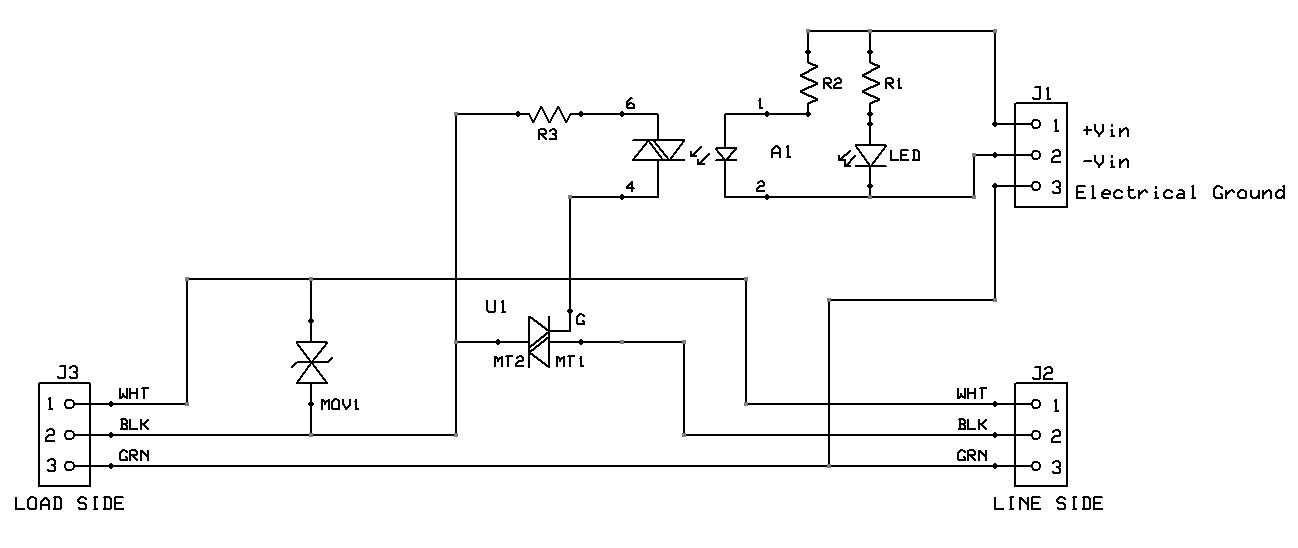
Power SSR Tail II Schematic
Two jumper wires attached to screw terminals are the digital control signal and logic ground. It will operate off of a 3.3V or 5V logic output signal and it draws about the same current as a small LED. Several Power Switch Tail modules could be used using mbed's USB cable power without the need for an external DC power supply for mbed.
Safety Note on High Voltages
Leave the cover on when using the module. A high voltage power line shorted to a digital logic circuit on a breadboard can blow up an entire computer system, or cause electrocution if touched. For safety, keep the wires for any high voltage and/or high current devices well away from the breadboard and do not touch them when power is on. Even a momentary wire short can blow things ups. An inline fuse and even a GFI breaker is not a bad idea. Long before a standard household AC circuit breaker trips, electronic parts will blow out with a short. Breadboard contacts and small jumper wires only handle about one amp. For electrical isolation, when using a relay to control external AC devices, do not connect the grounds on the power supplies from the control side to the load side.
Any digital out pin can be used to control the (SSR) solid state relay (connects to the input of the relay driver circuit).
Here is an example program the turns the relay on and off every 4 seconds.
#include "mbed.h"

DigitalOut myled(LED1);
DigitalOut Ctrl(p8);

int main() {
    while(1) {
        Ctrl = 1;
        myled = 1;
        wait(2);
        Ctrl = 0;
        myled = 0;
        wait(2);
    }
}
The digital output control signal (mbed P8) and a logic ground (mbed gnd pin 1) are connected using a small screw terminal block built into the case of the PowerSSR Tail. The AC connections use standard AC plugs. The digital signals are optically isolated from the AC load.
Wiring
| mbed | PowerSSR Tail | AC Device (<300W) | AC wall outlet |
|---|---|---|---|
| gnd | 2 -in | ||
| P8 | 1 +in | ||
| 3 (AC) gnd | |||
| AC female plug | AC male plug | ||
| AC male plug | AC wall socket |
Dimming Lights by adding a ZeroCross Tail
The PowerSwitch SSR version can dim lights when used with the zero crossing module (syncs to AC phase). The SSR version should not be used on inductive loads.

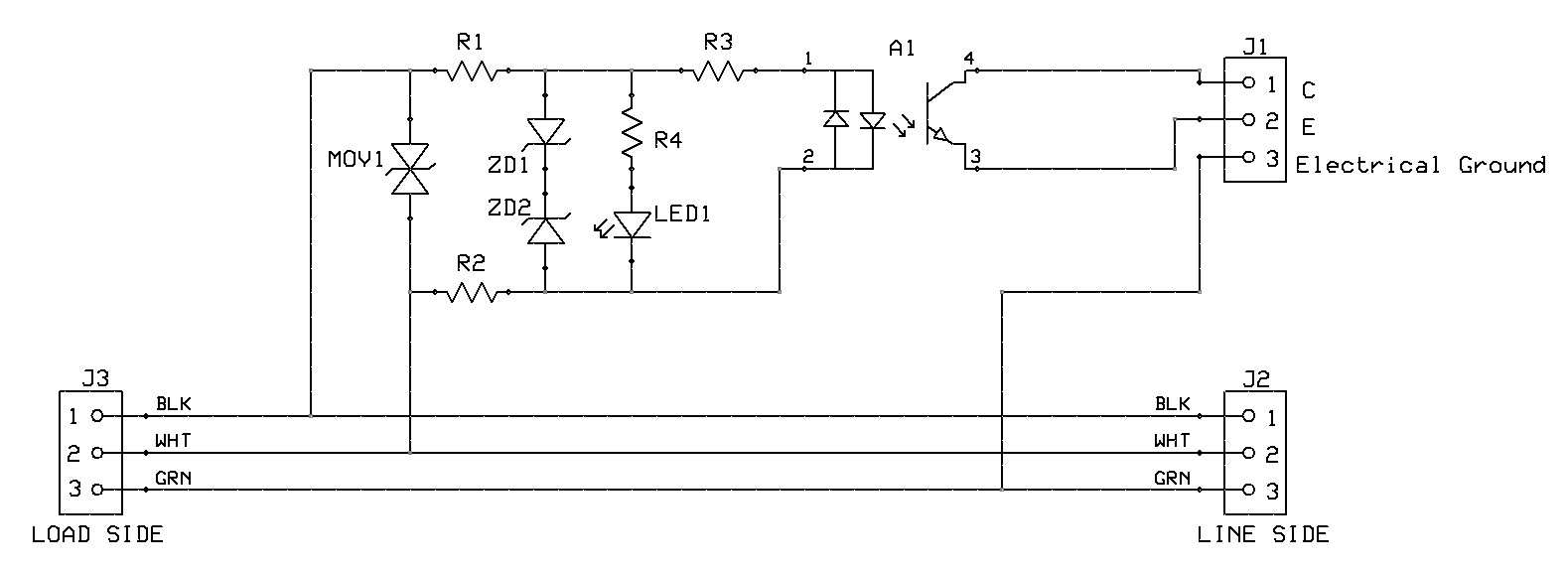
The ZeroCross Tail module detects AC line zero crossings

Larger Version
ZeroCross Tail Schematic
Code example using mbed to dim lights
The code example that follows will use the PowerSSR tail with the ZeroCross tail to dim a light. LED and fluorescent lights only work with a dimmer if they are designed to support dimming and stated to be "dimmable" on the box. Interrupts are used to detect zero crossing and also to control the "on" delay time to dim the light. The delay time needed must be synchronized to the zero crossing on the lights AC power line (hence the need for the ZeroCross module to support dimming). TRIACs are used in most low power dimmer circuits. TRIACs can only be turned off at an AC zero crossing.
Wiring
| mbed | PowerSSR Tail | AC Device | AC wall outlet | ZeroCross Tail |
|---|---|---|---|---|
| gnd | 2 -in | 2 E | ||
| P21 | 1 +in | |||
| P27 | 1 C with 1K to 10K pullup to mbed 3.3V (Vout) | |||
| 3 (AC) gnd | ||||
| AC female plug | AC male plug | |||
| AC male plug | AC wall socket | AC male plug |
#include "mbed.h"

PwmOut led(LED1); // led 1 indicates dim value
DigitalOut led2(LED2); // led 2 indicates delay time for interrupts

// pin for ZeroCross tail input
// An external 1K pullup required
InterruptIn zerocross(p27);

// pin for PowerSSRtail output
DigitalOut SSR(p21);

//use timer interrupts to control dimming
Timeout SSRtriggerOn;

// dimmer value 0.0=off and 1.0=full on
volatile float dim;

// AC power line frequency
const float powerlinefrequency=60.000;

// this interrupt routine is activated after a time delay set by dim value
void triggerOn()
{
    SSR = 1;
    led2=0;
}

// this interrupt routine is activated by every AC line zero crossing
// it is needed to synchronize the SSR turnon time delay to the AC line
void dimmer()
{
    // turn off SSR at zero crossing
    SSR = 0;
    // compute time delay using dim value and set timer interrupt
    // triggers SSR after a small post zero crossing time delay
    SSRtriggerOn.attach(&triggerOn,(1.001-dim)/(2*powerlinefrequency));
    led2=1;
}

int main()
{
    //set up interrupt routine to detect AC line zero crossings
    zerocross.mode(PullNone);
    wait(.2);
    zerocross.rise(&dimmer);
    // main program only sets dimmer level (dim)
    // interrupt routines dim the light
    while(1) {
        //increase brightness
        for(dim = 0.0; dim <= 1.0; dim += 0.025) {
            led = dim;
            wait(0.05);
        }
        //decrease brightness
        for(dim = 1.0; dim >= 0.0; dim -= 0.025) {
            led = dim;
            wait(0.05);
        }
    }
}
The video above runs the code example using a 100W light bulb attached to the PowerSSR Tail. The ZeroCross Tail interrupts mbed at each zero crossing (120Hz=2*60Hz). Mbed triggers the PowerSSR Tail's TRIAC at each AC line zero crossing after a time delay based on the dimmer setting (using a timeout interrupt). The net effect is that it can lower the AC voltage on the light bulb to dim it.
A single ZeroCross tail is all that is needed for several PowerSSR tails, since one can be used to synchronize all of the PowerSSR tail outputs.
There is also a PowerState module to detect if an AC device is turned on. Drivers, Relays, and Solid State Relays describes some other options and circuits to drive high current and/or high voltage AC and DC devices.
Please log in to post comments.
PowerSSR Tail and ZeroCross Tail
Page owner: jim hamblen
Created 08 May 2013.
Last updated 19 Sep 2019