LED lighting and sound effects for modelers and miniaturists
Scale modelers and miniaturists have been using LED lighting for several years. A few have had some basic analog blinking circuits. Recently, the availability of low-cost single chip microprocessors has even led to several commercial products which use PWM dimming control, timers, and firmware running on a microprocessor for more advanced LED lighting effects. This tutorial will examine some of the commercially available hardware, LED lighting effects, and show how they can be implemented with simple code examples.
Miniature Wonderland in Hamburg, Germany uses over 300,000 computer controlled LEDs for lighting effects.
Guliver's Gate recently opened in New York's Time Square. Over 600 artisans worked on the $40 million dollar exhibit.
Extremely small and bright LEDs are available with wire leads already soldered on, so LEDs can be used even for very small scale models. Small pre-wired LEDs and modules with some of these effects are also available from Evan Designs, Miniatronics, Bakatronics and Iron Penguin.
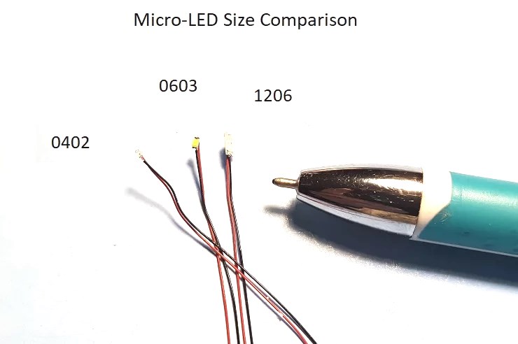
Tiny surface mount LEDs in pico, nano, and micro sizes with wire leads from Iron Penguin
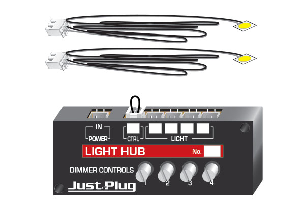
Woodland Scenics LED dimmer box
Woodland Scenics has a new LED lighting set that features a small control box with four potentiometers that can dim four Nano LEDs individually by using the analog input from each potentiometer to adjust the LED's brightness. Prewired LEDs plug into the box, and multiple boxes can be tied together to the power source along with a master control switch. It only supports initial dimming setups and does not have the more advanced lighting effects that will be described later. It is designed to provide building lighting for small models as seen in the small model town below. Even buildings and vehicles with pre-wired LEDs are now available for this system.
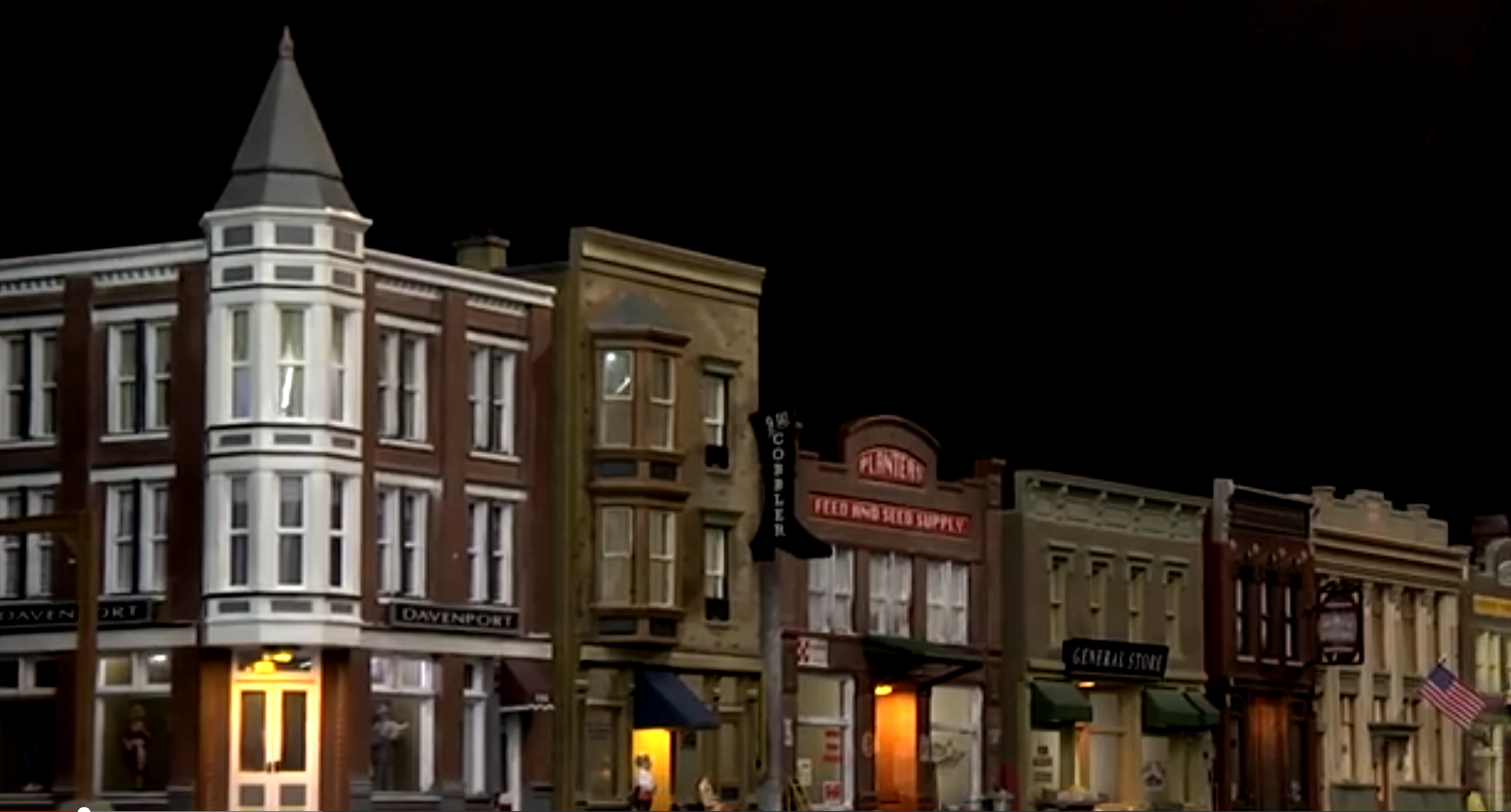
Miniature Town with a dimmable nano LED lighting system

An N scale downtown street scene using pre-wired LED buildings, street lights, and vehicles from Woodland Scenics. The buildings are about 2-3 inches high.
Using the mbed APIs PwmOut and AnalogIn with a small breadboard friendly potentiometer hooked up as a voltage divider between 3.3V and ground to an analog input, the following program would allow the potentiometer to dim the LED in a similar manner to the Woodland Scenics control box. Most mbed platforms have several analog inputs and PWM outputs, so multiple LED dimmer controls could be implemented on one device.
#include "mbed.h"
PwmOut myled(LED1);
AnalogIn mypotentiometer(p20);
int main()
{
    while(1) {
        myled = mypotentiometer;
        wait(0.01);
    }
}
For smaller home layouts, the tiny LED lighting effect board below from Iron Penguin contains a low-cost PIC SOC microprocessor, a full wave bridge rectifier, a 5V regulator and screw terminals to attach 6-12AC/DC power and LEDs.
Many new microprocessors have hardware PWM controllers and if they don't, PWM can also be done in software with timers and interrupts. A variety of these boards and LEDs from different sources can also be found at Walthers.
On the board seen below, with the full wave bridge rectifier circuit, 100uf filter capacitor, and small 5V regulator. The power needed can come from just about any old AC wall wart with an output in the range 6-12V AC or DC. Just cut off the connector, strip the wires, and hookup to the screw terminal (even the polarity does not matter with the full wave bridge circuit).Current draw for a single board is under 100MA.

A commercial board used for LED lighting effects
LEDs in model trains
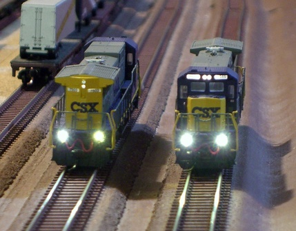
Model train engines have used LEDs lights for several years such as the N scale engines above. DCC systems can remotely control and dim the lights using a microprocessor. Many engine lights also change automatically when the train changes direction.
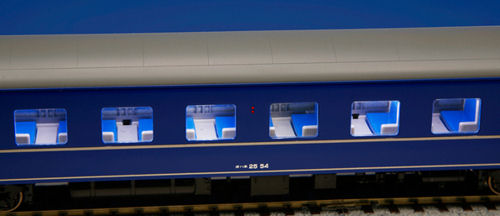
Many newer model train passenger cars are coming equipped with LED lights. Kato N scale model train passenger cars can be upgraded with internal LED lighting with a standard kit.

A white LED at one end of the car hooks to track power using the wheels and shines light into a special long plastic lens at the top of the car that spreads the light evenly through the car. An optional orange filter can be added to simulate incadescant lights in older trains.
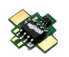
A tiny lighting control DCC decoder (microprocessor) can also be added inside the car to allow individual lighting control of each car in the train from the DCC remote train controller.
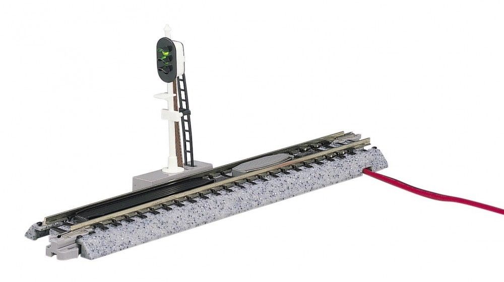
Automatic track semaphore signals are available with red, green, and yellow LEDs that indicate train locations using a sensor in the track.
LED Lighting Effects
Several LED lighting effects will be examined along with a code example for each one. Using the mbed APIs, PwmOut controls a hardware PWM output pin, and SoftPWM (Software PWM) can be used on any digital output pin. An value of “1.0” turns the LED on, and “0.0” turns it off. Anything in between will partially dim the LED (i.e., “LED=0.5;” would turn on the LED 50% of the time. This happens at such a fast rate that human vision does not perceive the flashes and only the average brightness level is perceived. "wait(seconds);" is used for time delays on mbed. The code examples are designed to be short and easy to understand and they not been optimized for performance. Further experimentation on algorithms is warranted and may lead to better lighting effects. The code examples are all setup for the mbed LPC1768 using the four onboard LEDs. On a different mbed platform, output pins used for LEDs will need to be changed.
Here is a selection of several LED effects which are relatively easy to implement on mbed with just a few lines of code.
Aircraft Warning Lights
Tall buildings, radio towers, and large power transmission lines are required to have aircraft warning lights. Older setups use red beacons and newer ones use white strobes. Some even use both and switch over from white to red during the night. Aircraft also have similar white anti-collision strobe lights, but newer ones have a double flash effect. Wing tips on aircraft also have red and green lights. A wide variety of commercial products to add LED lighting to small RC model aircraft is available.
White Strobes
White strobes typically flash in sequential order on a tower. A typical cycle takes 1.5 seconds. On real towers, they dim at night or switch over to red beacons. A few commercial model tower lighting kits now include light sensors to automatically switch lighting modes at night.
Here is a similar effect using the four builtin LEDs on the mbed LPC1768
#include "mbed.h"
//LED Tower Strobe Light Effect
//
BusOut myleds(LED1, LED2, LED3, LED4);
//groups 4 built-in LEDs digital outputs together
//on mbed LPC1768 - change pins for other platforms
int main()
{
    while(1) {
        int j=1; //one LED on at start of loop
        for(int i=1; i<16; i++) {
            //sends out digital values for all LEDs (0 or 1)
            myleds = j;
            //binary shift the 1-bit (1=LED on) left by one
            j = j<<1;
            //use wait to add a time delay close to a real tower light
            wait(0.093);
        }
    }
}
Import programLED_Strobe4
Demo of LED lighting effects using PWM and wait for time delays. Pins are setup for LPC1768 platform’s LEDs. For complete information, see http://developer.mbed.org/users/4180_1/notebook/led-lighting-effects-for-modelers/
Red Beacons
Red beacons flash on and off, but get brighter and dimmer. Older lights take time to warm up and cool down and some have soft start circuits to extend bulb life. They tend to get brighter and dimmer on a linear curve until they reach their full on or off levels. PWM can be used to simulate this effect. Note how the red warning beacon on top of the grain elevator in the video below gets brighter and dimmer. It does not just blink on and off.
Here is a similar effect using a PWM output with code to dim and time the LED
#include "mbed.h"
//LED Red Warning Beacon Lighting Effect
PwmOut myled(LED2);
//Use a PWM output to enable dimming
//1.0 is full on, 0.0 off, 0.5 50% on
int main()
{
    while(1) {
        //LED warm up effect using PWM
        for(int i=0; i<50; i++) {
            myled = i/50.0;
            wait(0.02);
        }
        //LED at full brightness level
        myled = 1.0;
        wait(0.25);
        //LED cool down effect using PWM
        for(int i=49; i>0; i--) {
            myled = i/50.0;
            wait(0.02);
        }
        //LED off
        myled = 0.0;
        wait(1.5);
    }
}
Import programLED_Beacon
Demo of LED lighting effects using PWM and wait for time delays. Pins are setup for LPC1768 platform’s LEDs. For complete information, see http://developer.mbed.org/users/4180_1/notebook/led-lighting-effects-for-modelers/
The two N gauge grain silos in the video below have red micro LEDs mounted on them and a dual red beacon lighting effect. The two beacons are synchronized to each other as is often done on nearby or large tall structures.
House and Building Lighting
Setups for house lights typically use several LEDs. One LED in a room can be set to randomly turn on and off every few minutes. A flickering blue LED can simulate lighting in a room with a large TV. Bars and night clubs can have several different colors of LEDs that flash on and off. Here is an example of house lighting with the TV effect and at the very end there is also a fire effect.
Here is the same idea using rand() (Cs random number function) to control the TV and the length of time between lights changing in two rooms. On the room lights in the code below, the closer the if statement's constant limit check value is to 1.0 the longer the average time will be between changes in the room lights. On some microprocessors, the real-time clock could even be used to schedule lights changing.
#include "mbed.h"
//LED House Lighting effect with flickering TV and room lights randomly changing
DigitalOut porch(LED1);
DigitalOut room(LED2);
DigitalOut room2(LED3);
//DigitalOut OK for LEDs just turning on and off
PwmOut TV(LED4);
//Need PWM for nice flickering TV effect

//Use Cs random number generator rand(), but scaled and
//converted to a float from 0.0 to 1.0
inline float random_number()
{
    return (rand()/(float(RAND_MAX)));
}

int main()
{
    float x=0.0;
    porch = 1;
    while(1) {
        x = random_number();
        TV = x;
        if (x >0.98) room = !room;
        if (x >0.99) room2 = !room2;
        wait(0.05);
    }
}
Import programLED_House_Lights
Demo of LED lighting effects using PWM and wait for time delays. Pins are setup for LPC1768 platform’s LEDs. For complete information, see http://developer.mbed.org/users/4180_1/notebook/led-lighting-effects-for-modelers/
Here is a video of the bar/disco/nightclub lighting effect using a flashing RGB LED. The flashing circuit is built into the LED. Several different color LEDs that flash on and off can also be used. Click on the small You Tube logo in the window to play this video.
Fire
A fire effect can be used for outdoor fires, fireplaces, and burning buildings. An orange LED is used with random brightness levels that change a bit slower than the welding effect. Sometimes a red LED is also used so that the fire color can also vary.
Here is a fire effect using C's random number generator. As an alternative to rand(), an array of constants could also be used for a random number sequence and it would be faster, but this one will not repeat for a very long time. This effect really needs an external orange LED.
#include "mbed.h"
//LED fire lighting effect
PwmOut myled(LED1);
//Use PWM output to enable LED dimming

//Use Cs random number generator rand(), but scaled and
//converted to a float (range 0.0 to 1.0) for PWM output
inline float random_number()
{
    return (rand()/(float(RAND_MAX)));
}

int main()
{
    while(1) {
//get a new random number for PWM
        myled = random_number();
//a bit slower time delay can be used for fire
        wait(0.04);
    }
}
Import programLED_Fire
Demo of LED lighting effects using PWM and wait for time delays. Pins are setup for LPC1768 platform’s LEDs. For complete information, see http://developer.mbed.org/users/4180_1/notebook/led-lighting-effects-for-modelers/
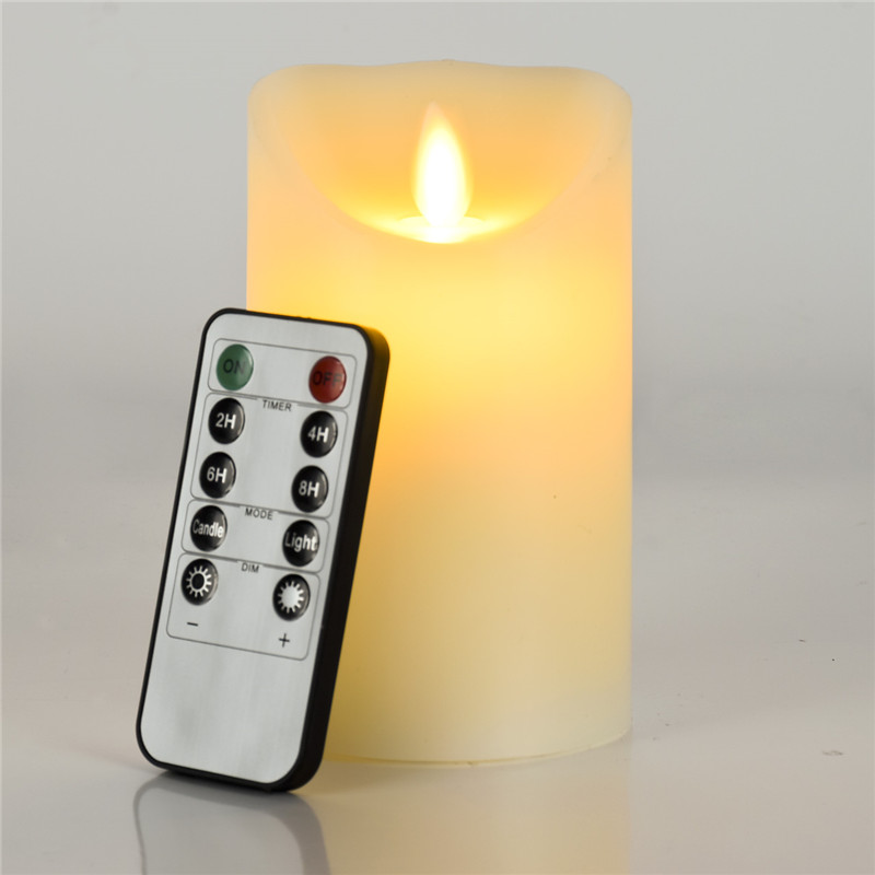
LED candles have a fire effect and some even have an IR remote that controls color, effects, timers, and dimming. LED candles with recheargable batteries are widely used now in restaurants instead of candles.
Arc welding
Models of factories, railroad maintenance buildings, and even gas stations can use an LED welding effect. A white LED is typically flashed on and off for random time durations. Welding is similar to the fire effect, but it is typically off for longer time durations and changes with a faster time constant. Sometimes a blue LED is also used with one or two white LEDs.
Here is a welding effect using C's random number generator. As in the fire effect, an array of constants could also be used for a random number sequence and it would be faster, but this one will not repeat for a very long time. It also includes a random time delay to pause between welds.
#include "mbed.h"
//LED welding lighting effect
PwmOut myled(LED1);
//Use PWM output to enable LED dimming

//Use Cs random number generator rand(), but scaled and
//converted to a float 0.0 to 1.0 for PWM output
inline float random_number()
{
    return (rand()/(float(RAND_MAX)));
}

int main()
{
    float x = 0.0;
    while(1) {
        //get a new random number for PWM
        x = random_number();
        //add some exponential brightness scaling
        //for more of a fast flash effect
        myled = x*x*x;
        //fast update rate for welding flashes
        wait(0.02);
        //add a random pause between welds
        if (random_number()>0.9925) {
            myled=0.0;
            wait(4.0*random_number());
        }
    }
}
Import programLED_Welder
Demo of LED lighting effects using PWM and wait for time delays. Pins are setup for LPC1768 platform’s LEDs. For complete information, see http://developer.mbed.org/users/4180_1/notebook/led-lighting-effects-for-modelers/
Emergency Vehicle Lights
Emergency vehicles such as police, fire, and ambulances have rotating lights and newer ones have red and/or blue flashing lights.
Here is some example code that simulates the emergency vehicle lights seen in the video. A regular digital output pin can be used, but the PWM outputs provide a smoother effect. Note that each light flashes three times, before changing to the other light.
#include "mbed.h"
//LED emergency vehicle lighting effect
PwmOut myled(LED1);
PwmOut myled2(LED4);
//Use PWM for dimming

int main()
{
    while(1) {
        //flash three times on LED1
        for(int i=0; i<3; i++) {
            //ramp up brightness level
            for(double x = 0.0; x <= 1.0; x = x+0.2) {
                myled = x*x;
                wait(.02);
            }
        }
        myled=0.0; //LED1 off
        //flash three times on LED2
        for(int i=0; i<3; i++) {
            //ramp up brightness level
            for(double x = 0.0; x <= 1.0; x = x+0.2) {
                myled2 = x*x;
                wait(.02);
            }
        }
        myled2=0.0; //LED2 off
    }
}
Import programLED_PoliceFire
Demo of LED lighting effects using PWM and wait for time delays. Pins are setup for LPC1768 platform’s LEDs. For complete information, see http://developer.mbed.org/users/4180_1/notebook/led-lighting-effects-for-modelers/
More LEDs can be added for larger emergency vehicles such as fire trucks and this snow plow seen below. These N scale ones from a detailed metal die cast kit are only two inches long and have 6 tiny surface mount nano and pico LEDs synchronized by one PIC microcontroller.
Lighthouse or Searchlight
A lighthouse typically cycles about every five seconds. The brightness level comes up and down, but with an exponential increase and not a simple linear curve. The 3-inch lighthouse model seen in the video below uses a PIC microprocessor-based lighthouse effect control board and a white micro LED.
Here is a code example for a lighting effect similar to the one seen in the video. A sine function is used along with time delays so that a cycle takes around 5 seconds. As an alternative to using sine, the code could ramp up and then ramp down the brightness level. It does however need an exponential rise and fall time with a sharp peak to resemble a lighthouse.
#include "mbed.h"
//LED Lighthouse or Searchlight lighting effect
PwmOut myled(LED1);
//use Pwm output for dimming

int main()
{
    float y=0.0;
    while(1) {
        for(double x=0.0; x <= 3.14159; x = x + 0.0314159) {
            y = sin(x); //nice periodic function 0..1..0
            myled = y*y*y;//exponential effect - needs a sharp peak
            wait(.025);
        }
        myled = 0.0;
        //most lighthouses have a 5 second delay - so add another 2.5
        wait(2.5);
    }
}
Import programLED_Searchlight
Demo of LED lighting effects using PWM and wait for time delays. Pins are setup for LPC1768 platform’s LEDs. For complete information, see http://developer.mbed.org/users/4180_1/notebook/led-lighting-effects-for-modelers/
Airport Beacons
A similar effect to the lighthouse but about twice as fast can be used for airport tower rotating beacons. Sometimes a green and/or red/yellow LED is used mounted on top of a white micro chip LED to simulate airport beacons that alternate between green and white beacons. Airport beacons flash about every 2 seconds. An RGB LED would also be handy for this one. They are actually color coded to indicate the type of airport:
◾Flashing white and green for civilian land airports
◾Flashing white and yellow for a water airport
◾Flashing white, yellow, and green for a heliport
◾Two quick white flashes alternating with a green flash identifying a military airport
◾White, green, and red flashes for a Hospital and/or Emergency Services Heliport
A lighting system for a model airport control tower. Note the white and then green flashes. Model runway lighting systems are also available.
Railroad and Traffic signals
Scale railroad and traffic signals are available including some with pre-installed colored LEDs. These LEDs can be controlled using a digital output pin along with timers in a microprocessor. If you want to warm up and cool down to simulate older incandescent lights, PWM can be used. Scale streetlights, crossing lights, and railroad signals are available from several sources such as N J International and Walthers
Here is an example program for driving two lights on a railroad crossing signal. Many still have the older incandescent bulbs that take time to warm up and cool down. Since this effect is needed on more than just one LED, this time a function was used to simulate an incandescent bulb's warm up and cool down cycle using PWM. In C++, a class with member functions could be used to setup pins and control lights. On mbed, a non-blocking call to Ticker or Timeout with interrupt callbacks could be used instead of waits, so that more than one LED could change at a time. As will be shown later, the RTOS can also be used with minimal changes.
#include "mbed.h"
//LED Railroad Crossing Lighting Effect
PwmOut myled(LED1);
PwmOut myled2(LED4);
//Use a PWM output to enable dimming
//1.0 is full on, 0.0 off, 0.5 50% on

//function to simulate incandescent bulb warm up
//and cool down cycles
void incandescent_bulb(PwmOut led, float on_time = 0.1,
float warm_time = 0.2)
{
    //LED warm up effect using PWM
    for(int i=0; i<10; i++) {
        led = i/10.0;
        wait(warm_time/10.0);
    }
    //LED at full brightness level
    led = 1.0;
    wait(on_time);
    //LED cool down effect using PWM
    for(int i=9; i>0; i--) {
        led = i/10.0;
        wait(warm_time/10.0);
    }
    //LED off
    led = 0.0;
}

int main()
{
    while(1) {
        incandescent_bulb(myled);
        incandescent_bulb(myled2);
    }
}
Import programLED_Railroad_Crossing
Demo of LED lighting effects using PWM and wait for time delays. Pins are setup for LPC1768 platform’s LEDs. For complete information, see http://developer.mbed.org/users/4180_1/notebook/led-lighting-effects-for-modelers/
Adjusting the overall Brightness of any LED effects
In some cases, it may turn out that the LEDs are actually too bright overall. All of the effects can be dimmed down by multiplying or scaling each new PWM output value by a brightness level that varies between 0.0 and 1.0. The program below shows the idea and makes it easy to experiment with different brightness settings:
#include "mbed.h"
PwmOut myled(LED1); //dimmable LED
int main() {
    const float brightness_level = 0.75; // set to 75%
    while(1) {
        for(float p = 0.0f; p < 1.0f; p += 0.1f) {
            myled = p * brightness_level;
            //scales down LED’s brightness by 75%
            wait(0.1);
        }
    }
}
Adding Sensors to trigger LED Lighting Effects
Sensors can be added to the microprocessor to trigger lighting effects. The small board below senses the current flow from a model train engine on nearby track segments and triggers the lights on the railroad crossing and also semaphores for trains.
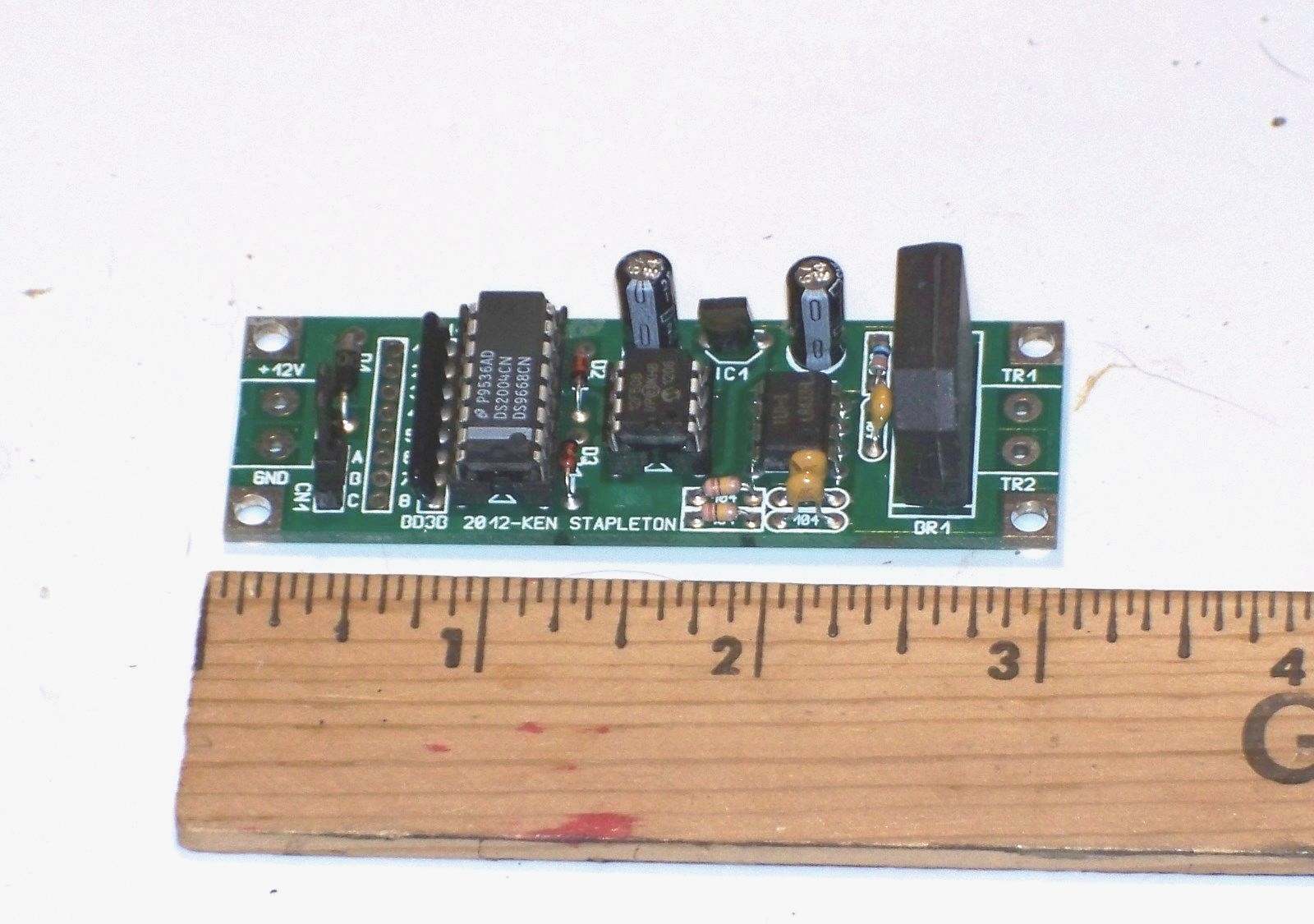
This board from Kens Model Railroad Electronics triggers LED railroad crossing lights when the engine is near.
The model railroad track must be divided into different power segments called “blocks”. The AC power to each block goes through two diodes connected in parallel but with reverse polarity on the second diode. There will be a small + or - voltage drop across the diodes whenever current to run an engine’s motor is flowing in that power block in either direction. A large full wave bridge rectifier in a single package (far right black block on board above) is typically setup for this purpose with two extra diodes in series to double the voltage drop to around 1.2V for easier sensing. For a block detection sensor using a bridge rectifier, the positive and negative terminals are tied together and the throttle power goes to one AC line pin and the other AC line pin goes to the track section used for block detection. It needs a rating of a couple amps or even more for larger scale railroads since all of the engine motor current must flow through it. A dual optoisolator (8 pin DIP next to PIC in photo) triggers on the small diode voltage drop and detects a nearby train. The two LEDs in the dual optoisolator are connected across the diode with reverse polarity on one to detect the current flow (voltage drop) in either direction. The optoisolator outputs are then used as sensor inputs to the microprocessor. In DCC train systems, a small transformer can be used for a block detection sensor instead of a diode such as the one found in these sensor modules from NCE.
A similar module for crossing signals is available from Walthers that uses optical sensors to detect the train.IR LED and IR detector module pairs are typically used. The IR beam can be interrupted or even reflected off of an object. One such small sensor from Sparkfun is seen below.

IR detector module from Sparkfun
A low-cost photocell or phototransistor (under $1) can be used to detect light levels in the room.
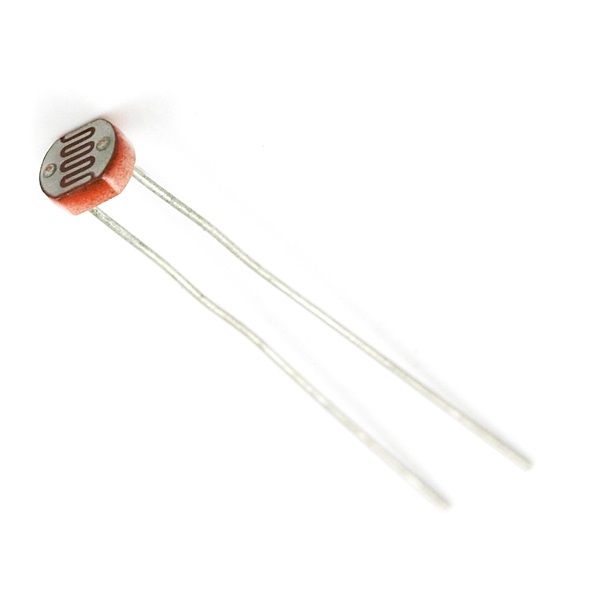
A low-cost Photocell can detect room lighting levels
A more complex light level sensor such as the one seen below could also be used to adjust the brightness level of LEDs by sensing current ambient lighting conditions or automatically change from daytime to nighttime lighting modes. There are several commercial LED lighting boards with light sensors that turn on LEDs used for streetlights when it is dark. One new radio tower lighting kit from Richmond Controls even uses a photocell to switch from white to red lights and dim automatically based on room lighting.
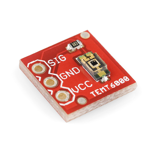
Light sensor breakout from Sparkfun.
A motion sensor such as the PIR (Passive Infrared) sensor seen below could be used to trigger lighting events when motion is detected nearby.
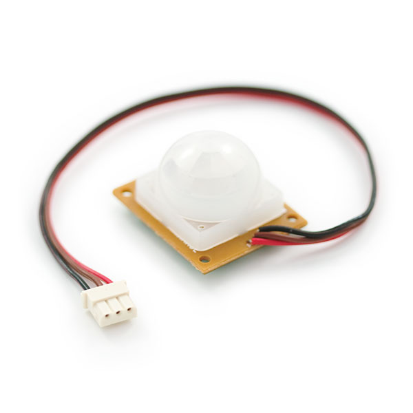
PIR motion sensor from Sparkfun
Using a small speaker and the microprocessor, sound effects can also be added. It is even possible to play *.wav sound files from an external SD card. There are numerous sources for recorded sound clips for model railroads and miniatures.
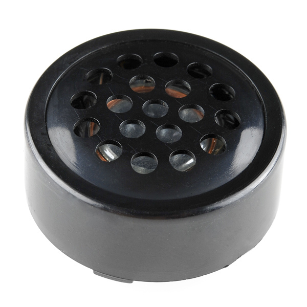
Sparkfun PCB or breadboard mount Speaker 8ohm .1W
Expanding PWM outputs for LEDs
There are low-cost I/O expander chips that can be used to add more hardware PWM outputs to control more LEDs from a single microprocessor. They can be used as an alternative to using multiple microprocessors to drive LEDs in a complex display. The chip seen below, a TLC5940, adds 16 hardware PWM outputs. It is also available in a smaller surface mount package and Sparkfun has a breakout board for it. Software drivers for this device are available in the mbed cookbook.

TLC5940 DIP package
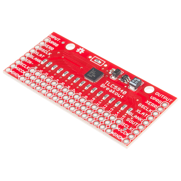
TLC5940 breakout board from Sparkfun
Another common I/O expander IC with PWM outputs used for driving up to 16 LEDs is the PCA9685. This chip is used on the Pi hat 16 servo control board seen below from Sparkfun. It was actually designed to control LEDs instead of servos, but will work with both. It uses an I2C interface and servo cables plug directly into header pins on the board.
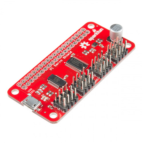
This board from Sparkfun controls up to 16 LEDs using I2C. Adafruit has a couple of similar boards that can control 16 LEDs. There is also an mbed library using the PCA9685
Using an RGB LED
An RGB LED can also change color by using three LEDs (Red-Green-Blue) and three PWM outputs in one small package. Using RGB LEDs contains code examples for mbed for discrete RGB LEDs. There are even new small versions that contain the PWM driver circuit and the 3 LEDS in one small package as seen below. These are just starting to appear in commercial products for miniature LED lighting. For larger versions, there are also small boards such as the Shiftbrite. Changing colors in addition to dimming could enhance several of the lighting effects especially the ones that often use several colors of LEDs. Even the white incandescent lighting effect could be improved some by adding a bit of yellow color to closer match the output of the real light. Most RGB LEDs with an integrated driver can be connected in a long chain and individually controlled. The components and cookbook pages have code examples for the tiny RGB LED module seen below along with several other RGB LEDs.
![]()
WS2812B 5050 RGB LED with Integrated Driver
Using the RTOS for multiple LEDs and effects
The current commercial LED lighting effects boards for model layouts and miniatures require a separate board with different firmware for each effect (i.e., welding, fire, beacon, lighthouse). With newer more capable microcontrollers, several can be combined on one board. While the individual lighting effects could be combined and turned into one monolithic chunk of code with a bit of re-work to schedule some complex random timing events and delays, the RTOS approach is easier once several asynchronous events start occurring with different time constants. If a system needs to drive multiple LEDs with different lighting effects and time delays, the easiest and quickest approach to scheduling is to use the RTOS. Each LED effect can be converted into a thread that is scheduled by the RTOS. The RTOS automatically time slices the processor among threads every millisecond. The RTOS time slicing gives the threads the external appearance that they are all running in parallel in an application. An application of course can wind up running too slow, if the threads require too much processor time, but that is not the case here.The LEDs do not need to be updated faster than every 10-20ms and the calculations are short in the LED code, so the RTOS will be effective in scheduling the threads and still running the LEDs in real-time with no noticeable difference. All "wait"s will need to be changed to a non-blocking call to "Thread::wait" so that other threads can run during the time delay (unlike "wait"). A "Thread::wait" prevents the RTOS from running the thread until the time period expires. The argument of "Thread::wait" is in milliseconds and not seconds as in "wait", so all time delays will need to be multiplied by 1000.
Unlike the mbed RTOS, a general purpose desktop OS such as Windows or Linux has a typical response time of 10-100ms (or even longer) and is too slow to prevent some occasional flicker in LEDs using complex PWM dimming effects.
Here is an example that drives all four LEDs using a different lighting effect code for each LED. Main is the first thread and it starts three more threads.
#include "mbed.h"
#include "rtos.h"
DigitalOut myled(LED1);
PwmOut myled2(LED2);
PwmOut myled3(LED3);
PwmOut myled4(LED4);

inline float random_number(){
    return (rand()/(float(RAND_MAX)));
}
void beacon(void const *args){
    while(1) {
        //LED warm up effect using PWM
        for(int i=0; i<50; i++) {
            myled2 = i/50.0;
            Thread::wait(1000.0*0.02);
        }
        //LED at full brightness level
        myled2 = 1.0;
        Thread::wait(1000.0*0.25);
        //LED cool down effect using PWM
        for(int i=49; i>0; i--) {
            myled2 = i/50.0;
            Thread::wait(1000.0*0.02);
        }
        //LED off
        myled2 = 0.0;
        Thread::wait(1000.0*1.5);
    }
}
void welding(void const *args) {
    float x = 0.0;
    while(1) {
        x = random_number();
        myled3 = x*x*x;
        Thread::wait(1000.0*0.02);
        if (random_number()>0.9925) {
            myled3 = 0.0;
            Thread::wait(1000.0*4.0*random_number());
        }
    }
}
void lighthouse(void const *args){
    float y=0.0;
    while(1) {
        for(double x=0.0; x <= 3.14159; x = x + 0.0314159) {
            y = sin(x);
            myled4 = y*y*y;
            Thread::wait(1000.0*.025);
        }
        myled4 = 0.0;
        Thread::wait(1000.0*2.5);
    }
}

int main() {
    //Start a thread to control each LED
    //RTOS schedules threads and has a 1MS time slice interrupt
    Thread thread2(beacon);
    Thread thread3(welding);
    Thread thread4(lighthouse);
    //main runs standard LED blink demo
    while(1) {
        myled = 1;
        Thread::wait(1000.0*0.2);
        myled = 0;
        Thread::wait(1000.0*0.2);
    }
}
Import programLED_RTOS
Demo of LED lighting effects using PWM and wait for time delays. Pins are setup for LPC1768 platform’s LEDs. For complete information, see http://developer.mbed.org/users/4180_1/notebook/led-lighting-effects-for-modelers/
Here is a version of the same demo setup to work with the new version 5.0 RTOS. It requires a firmware update to fix a bug with long wait times (LEDs flash too slow!). The code has only a couple minor changes with setting up threads and the preferred method to start threads is now .start() in the version 5.0 RTOS. In version 5, wait(sec) can be used for time delays in threads.
Import programLED_RTOS_VER5
LED effects demo for LPC1768 using version 5 RTOS Details at https://os.mbed.com/users/4180_1/notebook/led-lighting-effects-for-modelers/ - NOTE: Requires firmware update for proper wait times
Combining LED effects using the mbed RTOS. From left to right, standard blink, beacon, welding, and lighthouse effects.
The PWM period was increased for a clearer video to 1/10,000 (i.e.,myled.period(1.0/1000.0); ). The video camera can catch the LED in the PWM off state in a video frame occasionally and increasing the clock rate from the slow default solves this problem. This may also be a good idea, if the default rate is too low on a different mbed platform and flickering is noticeable.
Unlike the current commercial products that use a different microprocessor module for each lighting effect, it is possible to combine several of them easily by using the mbed RTOS.
To accomplish this task without the RTOS, the code for each effect could be combined in one sequential block and rewritten without waits so that all effects compute only the next value for their LED and main then waits for a periodic interrupt every 10ms or so (using the Ticker API). The interrupt routine sends the next value out to all LEDs, and sets a flag so that the LED effect code runs once more, computes the next value and then waits for the next interrupt. This could also be done without interrupts by constantly checking at the end of main to see when 10ms has elapsed using the Timer API. Either option would require rewriting and combining all of the effects code with this approach in mind. If networking is added to the LED lighting module for remote control, synchronization, and configuration, the RTOS will still be needed for many of the network driver options.
Adding Sound Effects
A wide array of commercial products is available to add sound to a model train layout and many new high-end train engines provide train sounds. Many of these require a different board with a different version of the firmware for each sound effect. With a more capable microcontroller, it is possible the produce sound effects in addition to LED lighting effects and control. Once the lighting effects have been converted to threads that run in the RTOS, another thread could be added to play sound effects using a speaker. The cookbook waveplayer code will read *.wav files from and SD card or a USB stick with the appropriate file system drivers added to the project along with the required connectors. The connectors for SD or USB are also available on breakout boards for use on a breadboard, if they are not provided on the mbed platform used. This example uses a USB flash drive attached to mbed that contains the *.wav files. Sound effects can be found on the web, and using a sound editor such as the free Audacity audio editor, they can be converted to simple *.wav files from other more complex formats such as MP3, converted from stereo to mono, and down sampled to 16Khz or lower. Some mbed platforms have internal flash drives, but in most cases it is too slow to play *.wav files since the USB controller chip that controls the mbed processor for debug must respond to commands to read and write internal flash. A speaker can be hooked up with an amplifier and connected to an analog output on mbed to play the sound. This example used an old set of PC speakers. As an alternative, a small speaker with an audio amplifier could be used to make the device small enough to fit inside a model building.
Here is a video showing several of the earlier LED lighting effects after conversion to threads with some added sound effects played by the mbed with the RTOS using another thread for sound.
LED lighting effects with added sound effects using multiple threads in the mbed RTOS
To run this demo, sound effect *.wav files need to be selected and placed on the USB flash drive for the program to play. Without the sound files, the demo will have an fopen() error and the LEDs will not change. The code is a bit too long to list here, so the only the new details of the first lighting and sound effect will be shown. The code segment below starts a new thread running the LED lighthouse effect, it then opens the sound file, and starts playing the wave file, "foghorn.wav". When end of file is reached the file is closed. A delay is added between foghorn sounds with Thread::wait(). After playing the sound effect again three more times in the for loop, the command thread.terminate() stops the thread with the LED lighthouse effect. The code then moves on to a similar section of code for each effect.
            //Lighthouse demo with foghorn
            Thread thread(lighthouse); //Start LED effect thread
            for(int i=0; i<4; ++i) {
                //open wav file and play it
                wave_file=fopen("/usb/foghorn.wav","r");
                waver.play(wave_file); //Plays *.wav audio file
                fclose(wave_file);
                Thread::wait(1925);
            }
            //end of lighthouse demo;
            thread.terminate(); //kills LED effect thread whan audio stops
The program link below contains a project with the complete code for the demo seen in the video using a USB flash drive to store the wave files.
Import programLED_effects_w_sound
LED PWM lighting effects with sounds played from *.wav files using threads and the mbed RTOS. For more info see http://developer.mbed.org/users/4180_1/notebook/led-lighting-effects-for-modelers/ .
The program link below is the same project with the complete code for the same demo, but it uses a uSD card (instead of USB) and only the DAC output. Watch out for different versions of the SD filesystem drivers, some generate compile errors or run too slow for audio playback. There are several versions around, this one uses a 10Mhz transfer clock (instead of 1Mhz). With newer fast uSD cards it can work up to 30Mhz with short breadboard leads. Use the "Import Program" link to get all the correct versions and don't update to be safe.
Waveplayer for mbed OS version 5
The wave player code does not currently work in the new mbed ver 5 RTOS. The newer audio player example for ver 5 could likely be used instead, but is also has an OS mutex runtime error currently on the LPC1768 (9/19). It is available at https://github.com/ARMmbed/mbed-os-audioplayer with a demo at https://os.mbed.com/docs/mbed-os/v5.13/tutorials/usb-wav-audio-player.html. An updated version of wave_player for OS 5.0 for the mbed LPC1768 that does run can be found at : https://os.mbed.com/users/HighTide/code/wave_player/ and a demonstration program can be found here: https://os.mbed.com/users/HighTide/code/waveplayer_v5_demo/. This version writes to a PWM output pin and directly to the DAC's registers (works on LPC1768 only) to avoid the current OS 5 mutex problem. Select the output needed (DAC or PWM) for your application and the other one can be deleted. Increasing the PWM clock rate to play audio from the default 50Hz can break some other PWM code such as (RC ) servos, if it is setup for the default 50Hz clock since all of the PWM outputs typically have only one clock. The SD file system drivers are added by a line in the project's mbed_app.json file now in version 5. It might also be a good idea to increase the SPI clock rate to read the SD card faster for audio playback using "sd.frequenecy(25000000);" after sd.init.
For simple devices that require only new a few seconds of audio, it is possible to use on-chip flash memory instead of a *.wav file on an uSD card for audio playback. See Using Flash to Play Audio Clips for examples and tools to use.
Examples of Recent Commercial Products
One new commercial product in the video above combines a strip of white LEDs and sound to produce a random thunderstorm with lightning for model layouts.
Some new LED aquarium lighting systems simulate sunrise, sunset, moonlight, random passing clouds, and lightning storms. A few are even starting to have Wi Fi remote controls.
This new Kato N scale model train track crossing, senses the train using IR reflective sensors, activates the gates with a solenoid, flashes the LEDs, and plays one of four different sound effects for the signal bell. It has a volume control pot for the speaker, a sensitivity pot for the IR sensor, and a pushbutton to select the sound effect.

This new passenger car train lighting control board from http://www.modeltraintechnology.com fits inside the top of each car and it responds to standard DCC train commands to turn on/off dim internal lights with PWM using an Atmel ATTINY85 microprocessor. In addition to the LEDs and microprocessor, it also contains switching power supply with a capacitor bank to reduce flicker since the power comes from a train track and momentary power loss is common when the car’s wheels are moving. It also available in versions with a MEMs accelerometer that turns on the lights automatically when the train car is moving as seen in the video below.
This new LED lighting control board form http://www.modeltraintechnology.com responds to standard DCC train commands to turn on/off dim 16 internal LED lights with PWM using an Atmel ATTINY85 microprocessor with an LED PWM driver IC inside this small 3 inch N scale building. In addition to basic PWM dimming, several of the boards support user selectable LED lighting effects like TV, fire, and searchlights.
Adding Remote Control and Networking
Remote control can easily be added using IR or RF devices. There is a wiki on using low-cost short range IR and RF remotes like those found in TV remotes and car key fobs with mbed. In a complex layout, several microprocessors may be needed to drive and connect all of the LEDs. At that point, networking could be added to adjust and synchronize different lighting effects between the microprocessors (i.e. switching from daytime to nighttime lighting, or fine tuning brightness levels). If only low bandwidth is needed, any serial connection could be used. If the microprocessor platform includes USB or full networking support, USB, Ethernet, or Wi-Fi could also be used. With a low cost Bluetooth module they can be controlled from a smartphone.
Additional Videos of LED Lighting
Many of the lighting effects that were described can be found in these additional videos from Miniature Wonderland. In addition to 300,000 LEDs, there are around 300 computer controlled cars, trucks, trains, and airplanes in the layout. Vehicles have on board path control and magnetic steering that follows a steel wire in the roadbed based on the Faller Car System . Vehicles automatically drive to charging stations behind the scenes whenever the battery gets low.
Plane fire at the Airport
Miami Nightclub Fire
Behind the Scenes in the Miniature Wonderland Control Room
Behind the Scenes in Guliver's Gate
More videos and details on the technology used in Miniature Wonderland can be found at their web page. Miniature Wonderland uses their own custom lighting effects boards with 24 outputs and 3A of current per board. Boards can be used standalone, downloaded with a new dimming or lighting effect profile stored in EPROMs, or chained together in a network using two wires and controlled by a PC. The real-time response of Linux or Windows did not provide flicker free operation of LEDs from a standard I/O port, so the data for dimming and effects during operation had to come from the lighting control boards and not the PC. So on large layouts, an IoT approach for LED lighting control boards does make sense and the RTOS is helpful when an application requires several asynchronous tasks.
Disneyland even has some interesting new technology using large scale LED lighting effects as seen in the videos below.
IR controlled RGB LED mouse ears at Disneyland with a TI microcontroller

Glow with the show devices all cost $25 at Disneyland
Air Force Drone Light Show - 500 Drones with RGB LEDs
3 comments on LED lighting and sound effects for modelers and miniaturists:
Please log in to post comments.

you must be a engineer,i think,explain so much information.. Could you tell me which type led strip you use more? I also know some knowledge of the led strip, ike 12v ws2815 addressable,like cs2803 breakpoint continue,like sk6812 rgbw,or 12v ws2811 side emitting led strip,hope we can talk that more.