Important changes to repositories hosted on mbed.com
Mbed hosted mercurial repositories are deprecated and are due to be permanently deleted in July 2026.
To keep a copy of this software download the repository Zip archive or clone locally using Mercurial.
It is also possible to export all your personal repositories from the account settings page.
Dependencies: HttpServer_snapshot_mbed-os
License
When you use this program, we judge you have agreed to the following contents.
本プログラムを使用する際は、以下の内容に合意した事になります。
Information
Japanese version is available in lower part of this page.
このページの後半に日本語版が用意されています.
Video Links on how to setup and run WebCamera Application:
Your video will be live at:
- https://youtu.be/loTD846FEL0 Part1
- https://youtu.be/uKm77l8kl3A Part2
- https://youtu.be/iwQ9RzwhDNI Part3
Overview
This is a sample program that works on GR-PEACH or GR-LYCHEE.
This is a web camera sample program. When accessing from the Web browser, the following will be displayed.
- Camera input picture
- Control screen of devices connected to the I2C bus
- LED control screen
Requirements
For GR-PEACH (via Wi-Fi):
- GR-PEACH
- GR-PEACH Wireless CAMERA Shield : OV7725
For GR-PEACH (via Ether):
- GR-PEACH
- One of the following
- GR-PEACH Wireless CAMERA Shield : OV7725
- NTSC analog camera
- MT9V111 and GR-PEACH AUDIO CAMERA Shield
- OV5642 and GR-PEACH AUDIO CAMERA Shield
- GR-PEACH Wireless CAMERA Shield : OV7725
For GR-LYCHEE (via Wi-Fi):
- GR-LYCHEE
How to use
Turn on the power to the GR-Board and start the terminal software.
The default value of the bow rate with mbed is 9600, and in this sample we use the baud rate 9600.
When you press the reset button of GR-Board, the scan result of Wifi will be output on Terminal. Please refer to the following link for usage of Terminal.
| ********* PROGRAM START *********** Network Setting up... Scan: No.0 Network: SSID_1 secured:WPA/WPA2 BSSID: xx:xx:xx:xx:xx:xx RSSI: -52 Ch: 1 No.1 Network: SSID_2 secured: Unknown BSSID: xx:xx:xx:xx:xx:xx RSSI: -67 Ch: 2 2 networks available. Please enter the number of the network you want to connect. Enter key:[0]-[1], (If inputting the other key, it's scanned again.) |
Enter the number of the network you want to connect from the keyboard. To select SSID_1, press "0" on the keyboard.
| [SSID_1] is selected. please enter the PSK. |
Finally, enter the password to connect to the network.
If the connection is successful, the IP address is output on Terminal.
| connecting... MAC Address is xx:xx:xx:xx:xx:xx IP Address is 192.168.0.2 NetMask is 255.255.255.240 Gateway Address is 192.168.0.1 Network Setup OK |
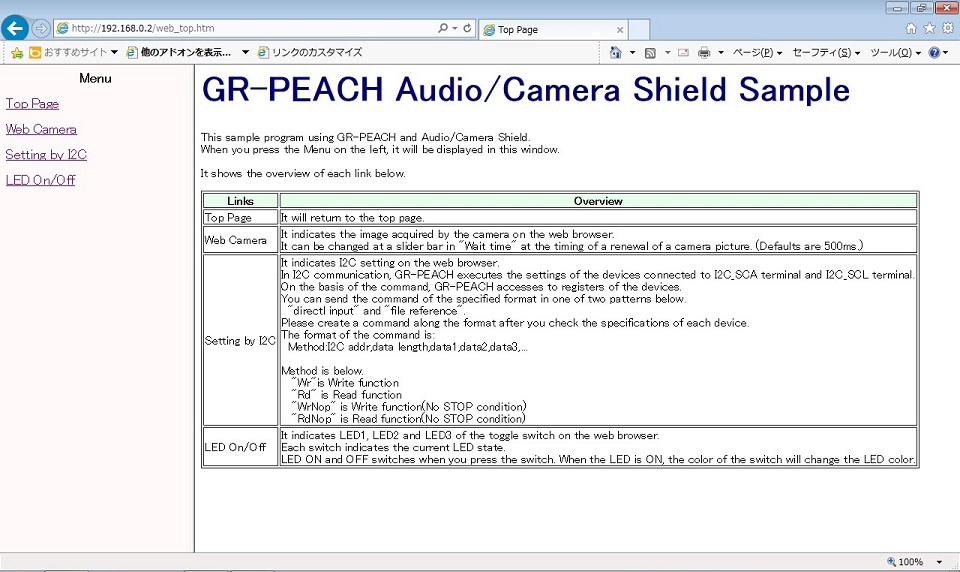
When you open IP Address ("192.168.0.2" in the above example) by a Web browser, top screen is indicated. The configuration of the top screen is a menu screen on the left side, a description screen of the sample program on the right side. If you click on each menu on the left side of the screen, the screen along the menu is indicated on the right screen.
Page Top

Web Camera

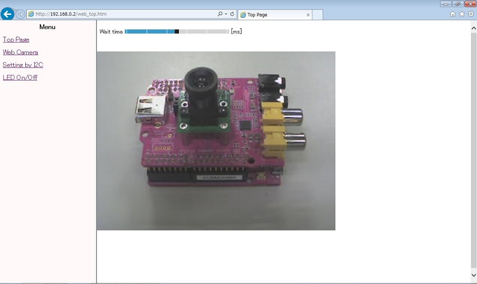
When you click the "Web camera" in the menu screen, the pictures of a camera is indicated. It can be changed at a slider bar in "Wait time" at the timing of a renewal of a camera picture. (Defaults are 500ms.)
Setting by I2C

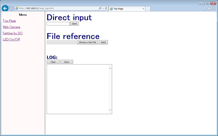
When you click the "Setting by I2C" of the menu screen, the control screen of the device connected to the I2C bus is indicated. By sending a command of a format listed below("Format of the device set by I2C") in Direct input or File reference, data transmission and reception is possible with respect to devices connected to I2C_SDA and I2C_SCL terminals of I2C. The communication log of transmission and reception by "Format of the device set by I2C" is displayed in the log window. When you press the "Clear" button, the log is cleared. When you press the "Save" button, the log is saved.
Format of the device set by I2C
| Method:I2C addr,data length,data1,data2,data3,... |
The details of each parameter is shown below.
For specific settings, check on the specifications of the connected device, you must create a command along the format.
| Method | Please specify one of the following: "Wr" ・・・ Write functions in I2C "Rd" ・・・ Read functions in I2C "WrNoP" ・・・ Write functions in I2C(No STOP condition) "RdNoP" ・・・ Read functions in I2C(No STOP condition) |
| I2C addr | Set the I2C address of device in hexadecimal. Ex: If the address is 0x90, set the "90" |
| data length | If Method is "Wr" or "WrNoP", set write size(the size of the data portion) in hexadecimal. Ex: If the write size is 2 byte(data1, data2), set the "02". If Method is "Rd" or "RdNoP", set read size in hexadecimal. Ex: If the read size is 10 byte, set the "0A". |
| data | If Method is "Wr" or "WrNoP", set write data in 1 byte unit in hexadecimal. Ex: If the write data is 0x01 0x02, set "01" in the data1 and "02" in the data2. If Method is "Rd" or "RdNoP", this parameter is omitted. |
An example of the format is shown below.
| Wr:90,03,25,45,14 |
To the device of the I2C address 0x90, the data write of 3Byte(0x25 0x45 0x14)
| Rd:90,02 |
To the device of the I2C address 0x90, the data read of 2Byte
LED On/Off

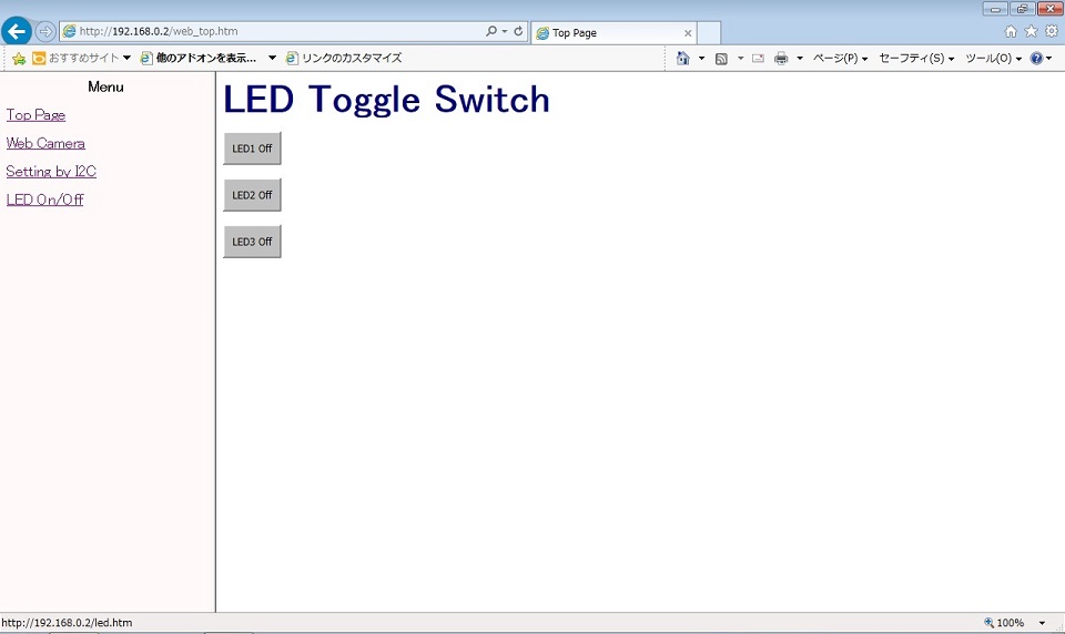
When you click the "LED On/Off" of the menu screen, the LED control screen is indicated. Each switch switches of GR-Boards to ON or OFF. Each switch indicates the current LED state. When the LED is On, the color of switch will change the LED color.
Switch to web page in SD card
Web pages displayed on the Web browser are located in the built-in ROM. file_table_peach.h is saved as table information for GR-PEACH and file_table_lychee.h is saved as table information for GR-LYCHEE. The contents of the saved file are as follows.
When connecting the SD card, SDBlockDevice will be displayed on the terminal and the web page displayed in the web browser will switch from the built-in ROM to the SD card. The top page is index.htm.
Change network connection
You can change the network connection by changing the following macro in main.cpp.
/**** User Selection *********/
#define NETWORK_TYPE           (2)                 /* Select  0(Ethernet), 1(BP3595), 2(ESP32 STA) ,3(ESP32 AP) */
#if (NETWORK_TYPE >= 1)
  #define SCAN_NETWORK         (1)                 /* Select  0(Use WLAN_SSID, WLAN_PSK, WLAN_SECURITY) or 1(To select a network using the terminal.) */
  #define WLAN_SSID            ("SSIDofYourAP")    /* SSID */
  #define WLAN_PSK             ("PSKofYourAP")     /* PSK(Pre-Shared Key) */
  #define WLAN_SECURITY        NSAPI_SECURITY_WPA_WPA2 /* NSAPI_SECURITY_NONE, NSAPI_SECURITY_WEP, NSAPI_SECURITY_WPA, NSAPI_SECURITY_WPA2 or NSAPI_SECURITY_WPA_WPA2 */
#endif
Depending on the value set for NETWORK_TYPE, the connection method changes as follows.
| Number | Connection | Description |
| 0 | Ethernet | GR-PEACH only |
| 1 | reserved | It can not be selected. |
| 2 | ESP32 STA | Use ESP32 in STA mode. |
| 3 | ESP32 AP | Use ESP32 in AP mode. |
When using GR-LYCHEE, NETWORK_TYPE 2 and 3 can be selected.
GR-PEACH Wireless CAMERA Shield is required separately when using ESP32 with GR-PEACH.
When using Ethernet, the user must provide the MAC address.
To specify MAC address, add fllowing function to main.cpp.
Specify MAC address
// set mac address
void mbed_mac_address(char *mac) {
    mac[0] = 0x00;
    mac[1] = 0x02;
    mac[2] = 0xF7;
    mac[3] = 0xF0;
    mac[4] = 0x00;
    mac[5] = 0x00;
}
Camera selection
To select the Camera, add camera-type to mbed_app.json.
See here for details.
mbed_app.json
{
    "config": {
        "camera":{
            "help": "0:disable 1:enable",
            "value": "1"
        },
        "camera-type":{
            "help": "Please see EasyAttach_CameraAndLCD/README.md",
            "value": null
        },
        "lcd":{
            "help": "0:disable 1:enable",
            "value": "0"
        },
        "lcd-type":{
            "help": "Please see EasyAttach_CameraAndLCD/README.md",
            "value": null
        }
    },
    "target_overrides": {
        "RZ_A1H": {
            "camera-type" : "CAMERA_WIRELESS_CAMERA"
        }
    }
}
Appendix
概要
GR-PEACH、および、GR-LYCHEEで動作するサンプルプログラムです。
Webカメラのサンプルです。Webブラウザからアクセスすると以下が表示されます。
- Camera入力画像
- I2Cバスに繋がっているデバイスの制御画面
- LED操作画面
構成
GR-PEACH (Wi-Fi経由)の場合:
- GR-PEACH
- GR-PEACH Wireless CAMERA Shield : OV7725
GR-PEACH (Ether経由)の場合:
- GR-PEACH
- 以下のいずれか
- GR-PEACH Wireless CAMERA Shield : OV7725
- NTSCアナログカメラ
- MT9V111 and GR-PEACH AUDIO CAMERA Shield
- OV5642 and GR-PEACH AUDIO CAMERA Shield
- GR-PEACH Wireless CAMERA Shield : OV7725
GR-LYCHEE(Wi-Fi経由)の場合:
- GR-LYCHEE
使い方
GR-Boardに電源を入れ、Terminalソフトを立ち上げます。
Mbedでのボーレートのデフォルト値は9600で、このサンプルではボーレート9600を使います。
GR-Boardのリセットボタンを押すと、Terminal上にWifiのスキャン結果が出力されます。
| ********* PROGRAM START *********** Network Setting up... Scan: No.0 Network: SSID_1 secured:WPA/WPA2 BSSID: xx:xx:xx:xx:xx:xx RSSI: -52 Ch: 1 No.1 Network: SSID_2 secured: Unknown BSSID: xx:xx:xx:xx:xx:xx RSSI: -67 Ch: 2 2 networks available. Please enter the number of the network you want to connect. Enter key:[0]-[1], (If inputting the other key, it's scanned again.) |
接続したいネットワークの番号をキーボードから入力します。0番のSSID_1を選択する場合はキーボードの "0" を押します。
| [SSID_1] is selected. please enter the PSK. |
最後にネットワークに接続するためのパスワードを入力します。
接続に成功すると、Terminal上にIPアドレスが出力されます。
| connecting... MAC Address is xx:xx:xx:xx:xx:xx IP Address is 192.168.0.2 NetMask is 255.255.255.240 Gateway Address is 192.168.0.1 Network Setup OK |
PCのWebブラウザで Terminalに表示された IP Address (上記例では 192.168.0.2)を開くと、トップ画面が表示されます。トップ画面は、左側にメニュー画面、右側にサンプルプログラムの説明画面という構成になっており、左画面の各メニューをクリックすると、メニューに沿った画面が右画面に表示されます。
Page Top 画面

Web Camera 画面

メニュー画面の”Web Camera”をクリックすると、Camera画像が表示されます。
"Wait time"のスライダーバーでCamera画像の更新タイミングが変更できます。(初期値は500msです)
Setting by I2C 画面

メニュー画面の"Setting by I2C"をクリックすると、I2Cバスに繋がっているデバイスの制御画面が表示されます。直接入力(Direct input)欄又はファイル参照(File reference)欄にて、下記("I2Cによるデバイス設定のフォーマット")に記載されているフォーマットのコマンドを送信する事で、I2CのI2C_SDA,I2C_SCL端子に繋がっているデバイスに対して、データの送受信が可能です。"I2Cによるデバイス設定のフォーマット"による送受信の通信ログは、ログウィンドウに表示されます。"Clear"ボタンを押すとログのクリア、"Save"ボタンを押すとログの保存ができます。
I2Cによるデバイス設定のフォーマット
| Method:I2C addr,data length,data1,data2,data3,... |
各パラメータの詳細を以下に示します。
具体的な設定値については、接続先のデバイスの仕様をご確認のうえ、フォーマットに沿ってコマンドを作成して下さい。
| Method | 以下のいづれかを指定して下さい "Wr" ・・・ I2Cでの書き込み "Rd" ・・・ I2Cでの読み出し "WrNoP" ・・・ I2Cでの書き込み(STOPコンディション省略) "RdNoP" ・・・ I2Cでの読み出し(STOPコンディション省略) |
| I2C addr | 接続先デバイスのI2Cアドレスを16進数で設定して下さい。 (例) アドレスが0x90の場合、"90"を設定 |
| data length | Methodが"Wr"又は"WrNoP"の場合、書き込むサイズ(data部分のサイズ)を16進数で設定して下さい。 (例) 書き込むサイズが2Byte(data1,data2)の場合、"02"を設定 Methodが"Rd"又は"RdNoP"の場合は読み取るサイズを16進数で設定して下さい。 (例) 読み取りサイズが10Byteの場合、"0A"を設定 |
| data | Methodが"Wr"又は"WrNoP"の場合、書き込むデータを16進数で1Byte単位で設定して下さい。 (例) 書き込みデータが0x01,0x02の場合、data1に"01"、data2に"02"を設定 "Rd"又は"RdNoP"の場合は省略して下さい。 |
フォーマットの例を以下に示します。
| Wr:90,03,25,45,14 |
I2Cアドレス0x90のデバイスに対して0x25 0x45 0x14の計3Byteのデータ書き込み
| Rd:90,02 |
I2Cアドレス0x90のデバイスに対して2Byteのデータ読み出し
LED On/Off 画面

メニュー画面の"LED On/Off"をクリックすると、LED操作画面が表示されます。各スイッチはGR-BoardのLED ON/OFFを切り替えます。スイッチはそれぞれGR-BoardのLEDの現在の状態を表しており、ONにすると対応するLEDの色になります。
SDカード内のWebページに切り替える
Webブラウザで表示されるWebページは内蔵ROMに配置されています。file_table_peach.h はGR-PEACH用、 file_table_lychee.h はGR-LYCHEE用のWebページがテーブル情報として保存されています。保存されているファイルの内容は下記の通りです。
SDカードを接続するとTerminal上に SDBlockDevice と表示され、Webブラウザで表示されるWebページが内蔵ROMからSDカードに切り替わります。トップページは index.htm となります。
ネットワークの接続方法を変更する
main.cppの下記マクロを変更することでネットワークの接続方法を変更できます。
/**** User Selection *********/
#define NETWORK_TYPE           (2)                 /* Select  0(Ethernet), 1(BP3595), 2(ESP32 STA) ,3(ESP32 AP) */
#if (NETWORK_TYPE >= 1)
  #define SCAN_NETWORK         (1)                 /* Select  0(Use WLAN_SSID, WLAN_PSK, WLAN_SECURITY) or 1(To select a network using the terminal.) */
  #define WLAN_SSID            ("SSIDofYourAP")    /* SSID */
  #define WLAN_PSK             ("PSKofYourAP")     /* PSK(Pre-Shared Key) */
  #define WLAN_SECURITY        NSAPI_SECURITY_WPA_WPA2 /* NSAPI_SECURITY_NONE, NSAPI_SECURITY_WEP, NSAPI_SECURITY_WPA, NSAPI_SECURITY_WPA2 or NSAPI_SECURITY_WPA_WPA2 */
#endif
NETWORK_TYPE に設定する値により、以下の接続方法に切り替わります。
| 番号 | 接続方法 | 説明 |
| 0 | Ethernet | GR-PEACHのみ。 |
| 1 | reserved | 選択できません。 |
| 2 | ESP32 STA | ESP32をSTAモードで使用します。 |
| 3 | ESP32 AP | ESP32をAPモードで使用します。 |
GR-LYCHEEを使用する場合はNETWORK_TYPE 2と3が選択できます。
GR-PEACHでNETWORK_TYPE 2と3を使用する場合は別途GR-PEACH Wireless/Cameraシールドが必要です。
NETWORK_TYPE 1のEthernetを使う場合はMACアドレスをユーザが用意する必要があります。
"main.cpp"の最後にの下記のように関数を追加し、用意したMACアドレスを設定してください。
Specify MAC address
// set mac address
void mbed_mac_address(char *mac) {
    mac[0] = 0x00;
    mac[1] = 0x02;
    mac[2] = 0xF7;
    mac[3] = 0xF0;
    mac[4] = 0x00;
    mac[5] = 0x00;
}
カメラの設定
カメラの指定を行う場合はmbed_app.jsonにcamera-typeを変更して追加してください。
詳細はこちらを参照ください。
mbed_app.json
{
    "config": {
        "camera":{
            "help": "0:disable 1:enable",
            "value": "1"
        },
        "camera-type":{
            "help": "Please see EasyAttach_CameraAndLCD/README.md",
            "value": null
        },
        "lcd":{
            "help": "0:disable 1:enable",
            "value": "0"
        },
        "lcd-type":{
            "help": "Please see EasyAttach_CameraAndLCD/README.md",
            "value": null
        }
    },
    "target_overrides": {
        "RZ_A1H": {
            "camera-type" : "CAMERA_WIRELESS_CAMERA"
        }
    }
}
付録
An error occurred while processing your request
no such method: docs