Static_Target
Static Target
Introduction
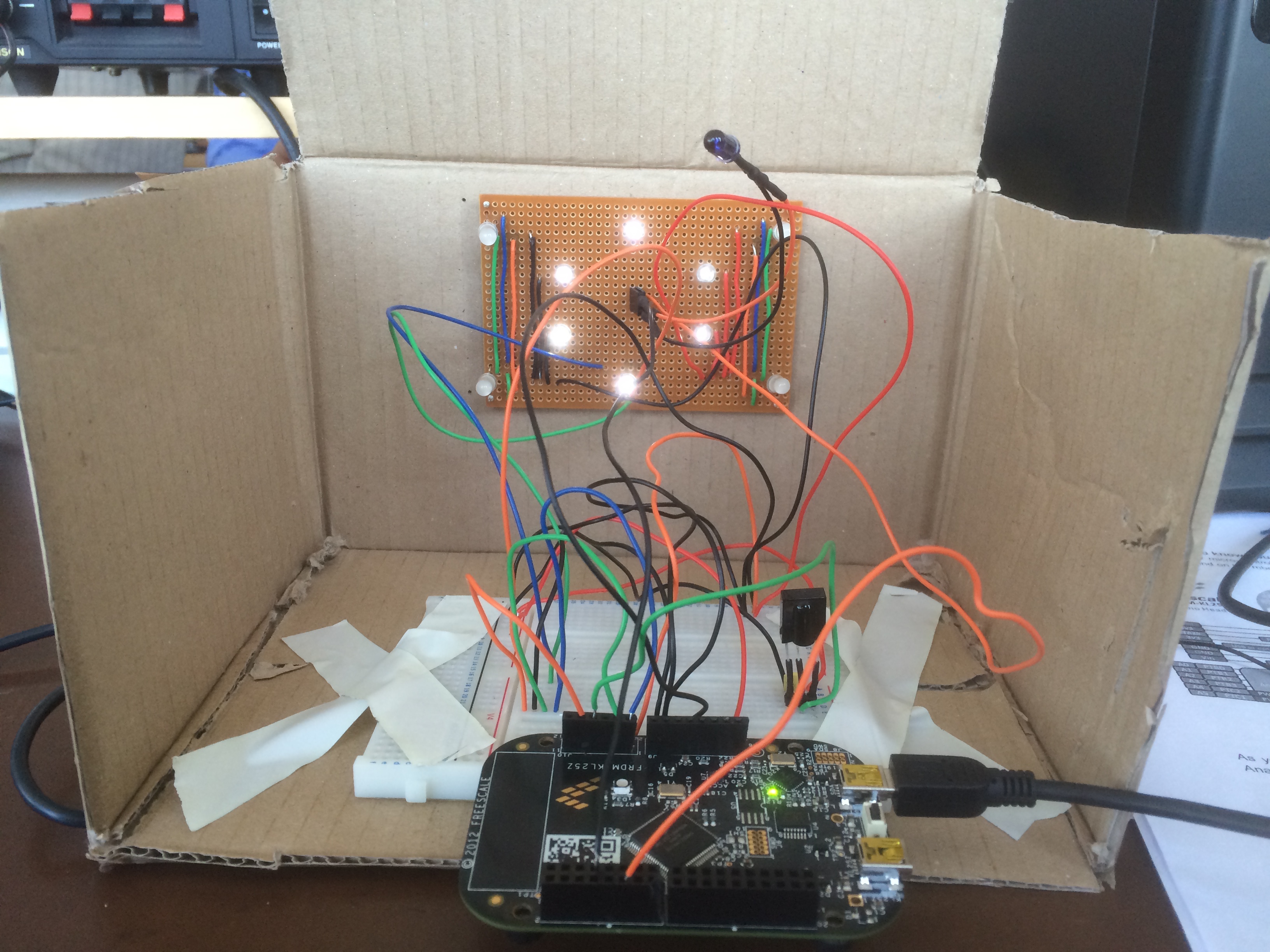
The static target acts as an extra point scorer for players. It consists of a tsmp1138 IR receiver capable of sensing IR signals from about 1-3m (depending on the intensity of transmission). It also uses a nRF24L01P wireless module to communicate with the scoreboard. The display for the static target consists of 6 white LEDs, 4 RGB LEDs, and an IR transmitter mounted on a veroboard. A bracket is used to present the display while ensuring connectivity to the mbed.
Components
- 1 FRDM KL25Z
- 1 tsmp1138 IR receiver
- 1 IR transmitter
- 6 white LEDs
- 4 RGB LEDs
- 1 3.3 nF smoothing capacitor
- 1 nRF24L01P Wireless Module
Functionality
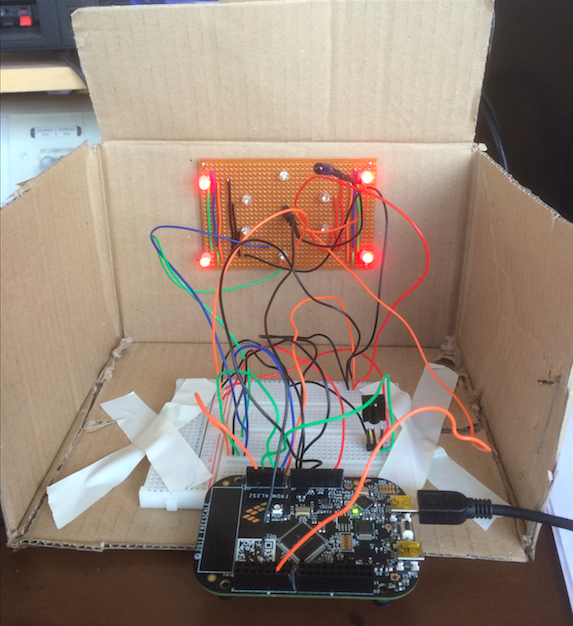
Using a random number generator, the static target activates spontaneously for a period of 10s. During those 10 seconds, the target can be shot (as shown by the white leds) and when it is shot, the target reads the id of its shooter and shines red, green or blue depending on which player shot the target. It also shoots back in a wide spray (acting like a bomb) so that players will not be allowed to wait in front of target to shoot it. As soon as it is shot, the target then deactivates. The target then communicates with the scoreboard to update the new scores.
Assembly of Display
NB. The arrangement is arbitrary. There is no restriction on the design; in fact there might be easier designs to solder on
- The white LEDs were arranged in an approximately hexagonal shape (the shape is completely arbitrary). Red power lines connecting the LED positive input to the mbed pin were soldered, alongside a common black ground line extending the range of the LEDs.
- The RGB LEDs were then soldered on the corners of the veroboard, with alignment of pins taken into account. The Red/Green/Blue lines were connected via Orange/Green/Blue wires, respectively (orange was substituted for red as red denotes the white LED power lines).
- Two pins were soldered in the middle of the hexagon for the IR transmitter (static shooter). These were connected to the mbed via orange and black wires (note that the orange wires in this line and the orange lines in the previous point are not related/connected in any way)
- Three pins were soldered near the centre of the hexagon for thr IR receiver. The 3.3nF capacitor was, however, placed on the breadboard directly, as the tracks close to the IR transmitter needed to be cut. A purple wire was used to connect the receiver to the mbed, while white was used for a 3.3v power source. The common ground wire was also used for the IR receiver.
- The display was then placed on the front of the cardboard, such that the breadboard and the mbed were placed behind the display.
- Wires connecting the display to the breadboard were then connected securely to the breadboard.

