Laser Guns
Introduction
The laser guns are one central part of the Laser Tag game. The overall body was produced using a 3D-printer. It has holes that allow to mount different features onto the gun. These features include a power supply (9V battery), a 10 bar LED showing the current status of the player (alive/dead, bullets remaining before reloading is required), a trigger, an IR emitter shooting the "bullet beams", and a buzzer making shooting sounds when the trigger is pulled. All these features are controlled by the FRDM-KL25Z development platform, which also communicates with the body armour via a serial bus.
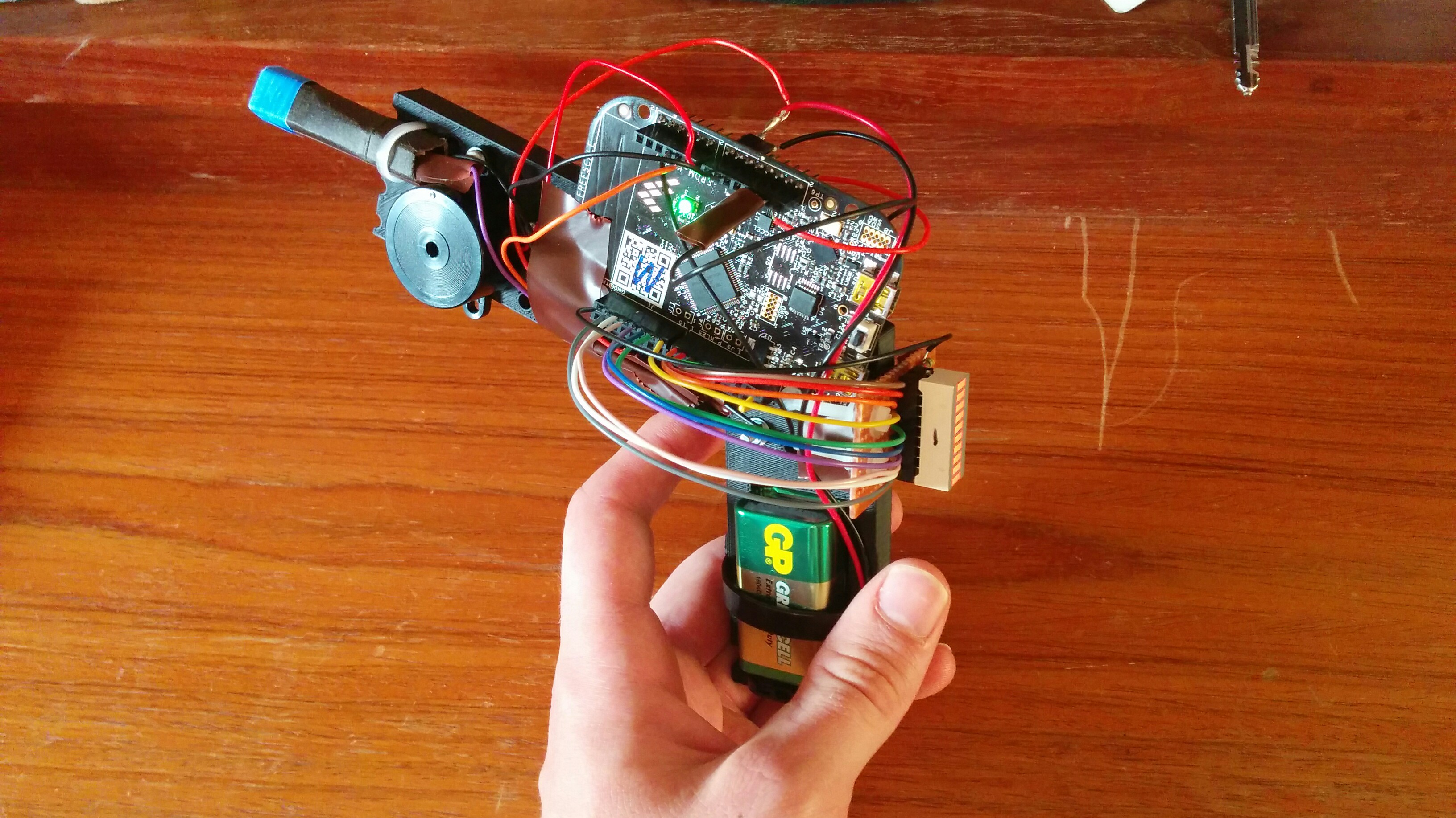 assembled and activated laser gun
Components (per gun)
- Microcontroller board (FRDM-KL25Z)
- Electronics components
- Microswitch PTM (for the trigger)
- Buzzer
- Transistor BC182L
- 10kOhm resistor
- IR emitter (TSUS5402 5mm)
- 20 pin DIL socket
- 10 LED bar (LEDTECH LL10000-G)
- 10 43Ohm resistors
- 9V battery
- Battery clip
- 2-pin female connector
- Veroboard (30x50mm)
- Insulating tape
- Solid core wire
- Stranded core wire
- Housing
- Gun chassis (3D printed or wooden)
- 2 cable ties
- 2 metal brackets
- 8 metal bolts
- 8 metal washers
- 10 metal nuts
- 4 nylon bolts
- 4 nylon washers
- 6 nylon nuts
Note: Some nuts were used as spacers
Note: All bolts,washers and nuts used were M3
Functionality
Once the gun receives the game start signal via the serial bus connecting the body armour, the gun is loaded with 10 bullets displayed as ten shining LEDs on the status display. When pulling the trigger, "bullets" are fired, which is heard accoustially via the buzzer and seen visually by the LEDs on the status display switching off from the top to the bottom. Once all bullets are fired, the player has to reload his/her laser gun by tilting it towards him/her. If done correctly, the gun reloads 10 bullets, which again can be seen on the LEDs on the status display. When the player is shot, the body armour sends a signal that disables the gun, which results in the LEDs on the status display flashing in turn for 30 seconds in which the player cannot shoot. After these 30 seconds, the player gets 10 new bullets and can continue the game.
Assembling the gun
1. Start with a 3D printed (or wooden) housing similar to this one with holes to fit M3 bolts and a space for a 9V battery. Make sure to include two extra holes, 55mm apart, to mount the microprocessor board.
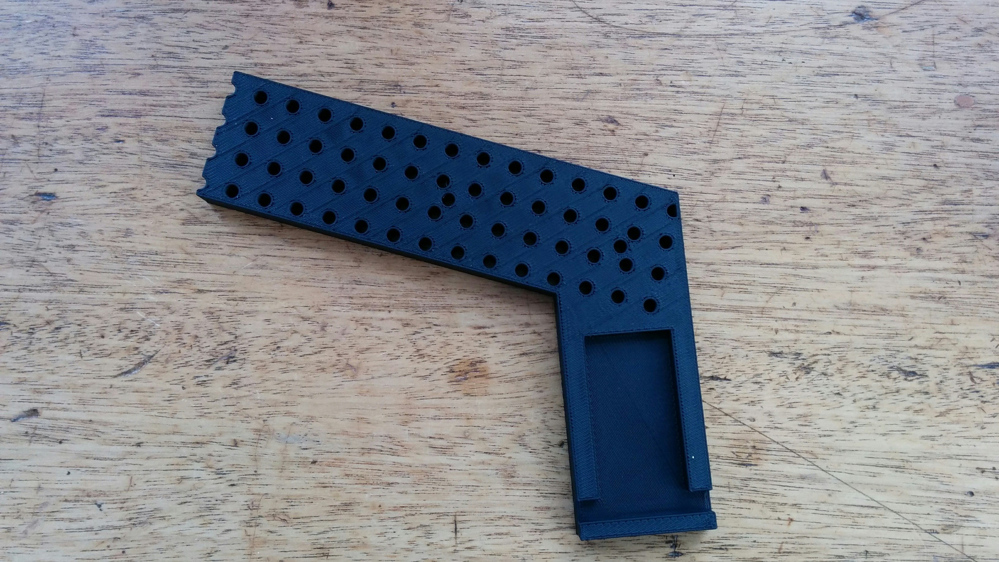
gun chassis
2. Add the 9V battery and angular brackets.
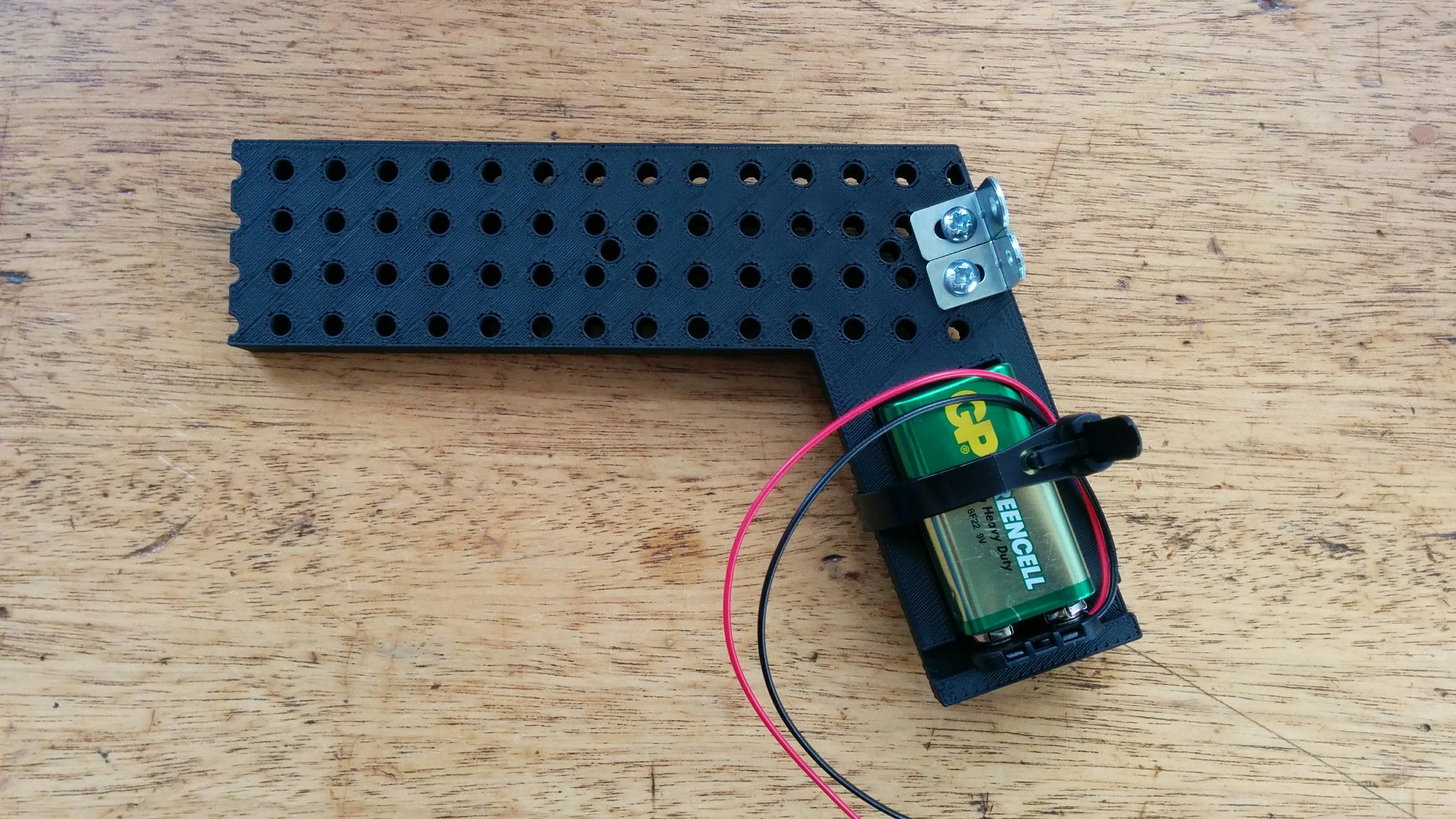
chassis with battery and brackets
3. Attach the microswitch in a position so it can be used easily as a trigger (make sure you wire up your leads so as to use the normally open terminal on the microswitch).
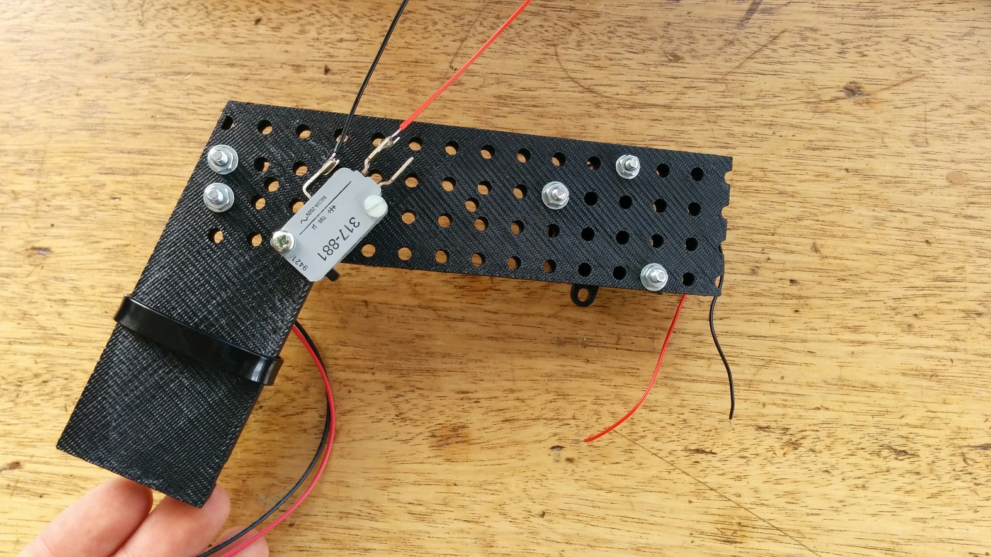
mounted trigger

circuit diagram for the trigger
4. Add the buzzer.
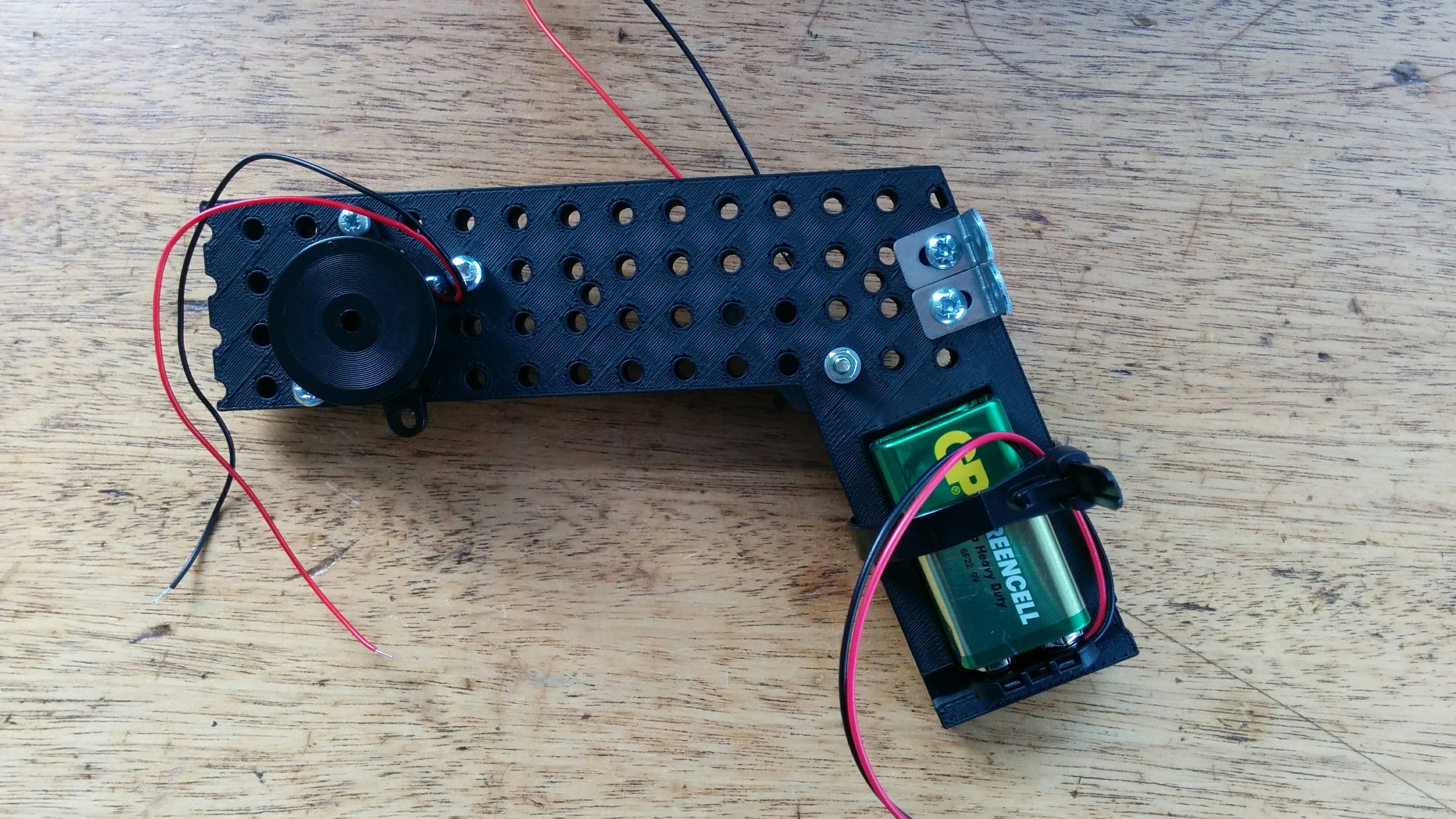
mounted buzzer
5. Screw on the Microcontroller using nylon bolts.
6. Solder on a 10k resistor on to the 0V foot of the microcontroller.
7. Drill two holes in the veroboard, solder on the 20 pin DIL holder,10 x 43Ohm resistors and 10 solid core wires on the negative side of the LEDs. Now solder all the resistors together at the positive end and then solder one wire to this common connection.

circuit diagram for LED bar
8. Now solder the IR emitter to the 9V power supply and to the collector of the transistor. The base of the transistor needs to be soldered to the 400Ohm resistor, which in turn is soldered to a pin on the microprocessor board that can be set to 3.3V or 0V. The emitter of the transistor is grounded.

circuit diagram for IR emitter
9. Roll a barrel out of cardboard (or alternatively paper) and put it over the IR emitter.
10. Finally trim all the wires down to a reasonable length and tape down anything loose.
 ready and activated gun
Program the Microcontroller
Plug in the microcontroller using a USB cable, import the code below as well as the MMA8451Q library, compile it and then save it on to the microcontroller.
Note: This is Laser_Gun_6 and it is the most recent code for the laser gun without the serial connection, which (dis)ables the gun and allows the gun to send a bullet count to the armour. Laser_Gun_7 includes this connection and is included further below.
Code goes here....
Brief outline of how the code works
The program runs round in a loop indefinitely. Inside the loop the program checks if the gun is in a disabled state (decided by the variable 'disableGun'). If it is disabled, the gun stays in a state where it only shows an animation on the LEDs and does not respond to any pressing of the trigger. Then the gun checks if the conditions for reload are met (the acceleration in the x-direction is above an absolute value of 1.95g). If so, the gun displays a loading amunition animation on the LEDs. And finally the main loop then checks to see if the trigger is pressed and there is amunition in the magazine. If so, the gun sends a character out the IR emitter. Different characters are used by different guns so as the armour can distiguish which gun shot them.
Test the Microcontroller
Remove the USB cable and put the connector from the battery on the V+ and GND pins so the board switches on.
Adding the Serial Connection to the Armour
Additional Components:
- 5 core wire
- connectors
Connect up the TX pin of the gun to the RX pin of the armour. Analogously, the RX pin of the gun goes to the TX pin of the armour. Connect up the flag output pin of the armour to the flag inout pin of the gun. Compile the advanced program below onto the microcontroller:
Code goes here too
Pins And Their Respective Functions
| Pin | Function |
|---|---|
| PTE20 | carrier |
| PTE22 | TX |
| PTB8 | trigger |
| PTB_11 | ground |
| PTC0,PTC3,PTC4,PTC5,PTC6,PTC10,PTC11,PTC12,PTC13,PTC16 | LED bar elements 1 to 10 |
| PTC7 | pos |
| PTE5 | buzzer |
| PTE4 | gnd3 |
| PTE25,PTE24 | MMA8451Q acc |