Important changes to forums and questions
All forums and questions are now archived. To start a new conversation or read the latest updates go to forums.mbed.com.
9 years ago.
Problem with the SPI clock on D13
Hello,
I'm working on an STM32F7 Disco and I need to use the NFC Shield v2.1. I've already made it work on an Arduino Uno, and i managed to recover the NFC Tag of NFC badge.
I now need to use this shield in the same way with my STM32F7 Discovery board. I managed to initialize the SPI2 (D11, D12, D13 Pins) but the NFC Shield ins't reconized.
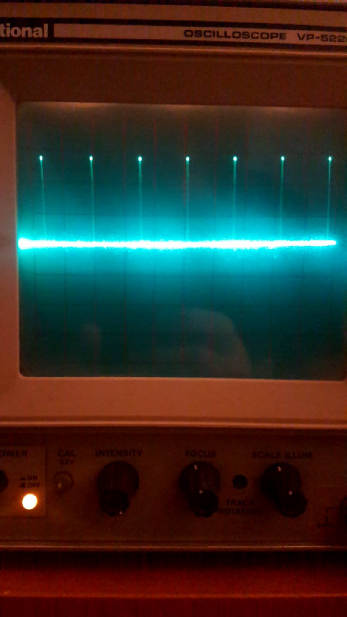
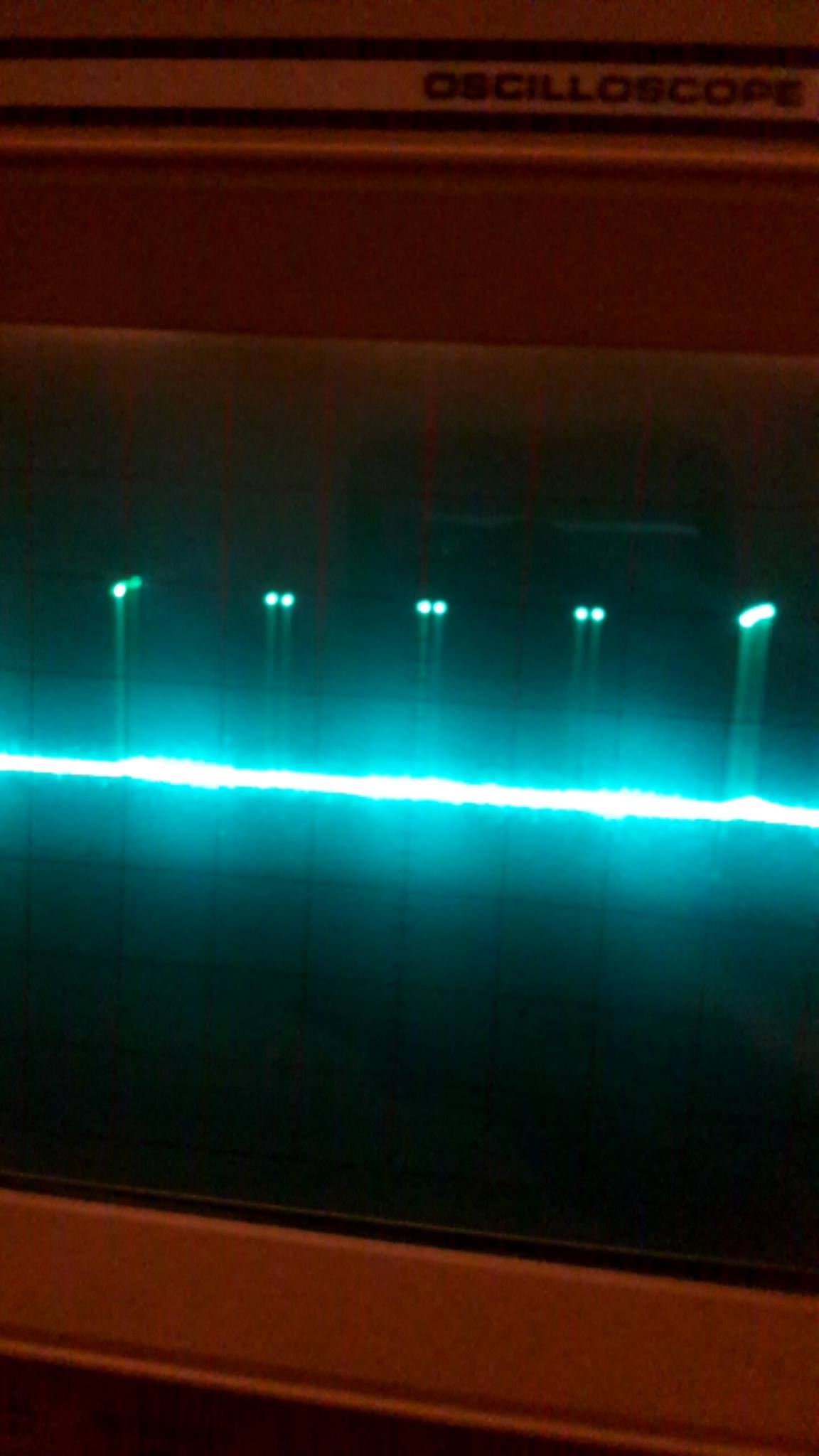
I think it's because of the SPI Clock, which amplitude is way too low, compared to Arduino Uno's SPI Clock. (like 2,5V for the STM32, and 5V for the Arduino).
I don't know if it's because of the way i initialized it, or because the SPI librairie of Mbed ins't appropriate with an STM32F7 board.
Here is my code :
SPI spi(D11, D12, D13); // mosi, miso, sclk

DigitalOut cs(D10);

PN532_SPI pn532spi(spi, D10);
PN532 nfc(pn532spi);

LCD_DISCO_F746NG lcd;
uint32_t    ErrorCounter = 0;

/* Private function prototypes -----------------------------------------------*/
void SystemClock_Config(void);
void Error_Handler(void);
//static void MX_GPIO_Init(void);
//static void MX_SPI2_Init(void);

int main(void)
{
    HAL_Init();

    SystemClock_Config();

 // MX_GPIO_Init();
 // MX_SPI2_Init();

    spi.lock();

    cs = 0;

    spi.format(8,0);
    spi.frequency(1000000);

    lcd.Clear(LCD_COLOR_WHITE);
    lcd.SetTextColor(LCD_COLOR_BLACK);
    lcd.SetBackColor(LCD_COLOR_CYAN);
    lcd.SetFont(&Font20);
    lcd.DisplayStringAt(0, 100, (uint8_t *)"TEST SPI", CENTER_MODE);

    spi.write(0xFFFF);

    nfc.begin(); // begin NFC communication


    HAL_Delay(1000);

    uint32_t versiondata = nfc.getFirmwareVersion();
    if (! versiondata)
    {
        lcd.DisplayStringAt(0, 20, (uint8_t *)"MODULE NON DETECTE 2", CENTER_MODE);
        nfc.mifareclassic_FormatNDEF();
        while (1);
    }
    nfc.SAMConfig();

    HAL_Delay(1000);

    lcd.DisplayStringAt(0, 100, (uint8_t *)"TEST NFC BEGIN", CENTER_MODE);

    HAL_Delay(1000);

    while (1)
    {
        spi.write(0x8F);
    }

}

void SystemClock_Config(void)
{
  HAL_StatusTypeDef ret = HAL_OK;
  RCC_ClkInitTypeDef RCC_ClkInitStruct;
  RCC_OscInitTypeDef RCC_OscInitStruct;

  /* Enable Power Control clock */
  __HAL_RCC_PWR_CLK_ENABLE();

  /* The voltage scaling allows optimizing the power consumption when the device is
     clocked below the maximum system frequency, to update the voltage scaling value
     regarding system frequency refer to product datasheet.  */
  __HAL_PWR_VOLTAGESCALING_CONFIG(PWR_REGULATOR_VOLTAGE_SCALE1);

  /* Enable HSE Oscillator and activate PLL with HSE as source */
  RCC_OscInitStruct.OscillatorType = RCC_OSCILLATORTYPE_HSE;
  RCC_OscInitStruct.HSEState = RCC_HSE_ON;
  RCC_OscInitStruct.PLL.PLLState = RCC_PLL_ON;
  RCC_OscInitStruct.PLL.PLLSource = RCC_PLLSOURCE_HSE;
  RCC_OscInitStruct.PLL.PLLM = 25;
  RCC_OscInitStruct.PLL.PLLN = 400;
  RCC_OscInitStruct.PLL.PLLP = RCC_PLLP_DIV2;
  RCC_OscInitStruct.PLL.PLLQ = 8;
  ret = HAL_RCC_OscConfig(&RCC_OscInitStruct);
  ASSERT(ret != HAL_OK);

  /* activate the OverDrive to reach the 180 Mhz Frequency */
  ret = HAL_PWREx_ActivateOverDrive();
  ASSERT(ret != HAL_OK);

  /* Select PLL as system clock source and configure the HCLK, PCLK1 and PCLK2
     clocks dividers */
  RCC_ClkInitStruct.ClockType = (RCC_CLOCKTYPE_SYSCLK | RCC_CLOCKTYPE_HCLK | RCC_CLOCKTYPE_PCLK1 | RCC_CLOCKTYPE_PCLK2);
  RCC_ClkInitStruct.SYSCLKSource = RCC_SYSCLKSOURCE_PLLCLK;
  RCC_ClkInitStruct.AHBCLKDivider = RCC_SYSCLK_DIV1;
  RCC_ClkInitStruct.APB1CLKDivider = RCC_HCLK_DIV4;
  RCC_ClkInitStruct.APB2CLKDivider = RCC_HCLK_DIV2;

  ret = HAL_RCC_ClockConfig(&RCC_ClkInitStruct, FLASH_LATENCY_5);
  ASSERT(ret != HAL_OK);
}
Here is the Arduino SPI Clock

and here is the STM32F7 SPI Clock

The volt/div is the same for the 2 pictures. Thank you for your help.
Question relating to:

3 Answers
9 years ago.
Hi Eric. A general suggestion - forget about the NFC board for now. Instead, use the mbed libraries / examples to communicate with the onboard SPI flash memory device. Confirm that you are able to at least read from this SPI memory device. Even though the flash memory is QSPI (quad SPI) - the same flash memory should be fine to operate in the standard and slower SPI mode. This will confirm that the mbed library for SPI is operation if you can read out say the flash memory IDs and compare the ID values against the datasheet for the same flash device. After this is confirmed, then proceed to work with your NFC board. Confirm the pinouts start and land on your shield board correctly. The voltage swing is fine for 3v3 operating processors. You can also validate each of the SPI port pins by simply toggling like a LED blinky at slow speed and confirm that the respective port pin does indeed swing to 3v3 or 0.
9 years ago.
Typical Arduino is a 5V device, that is why you see the 5V swing. The STM32F7 and other ARM processors are 3V3 devices. Did you confirm that your NFC shields works at 3V3 powersupply and/or 3V3 controlsignals. Most devices will work at 5V power and with a 3V3 signallevel.
Well, the NFC Shield work with a 5V power supply. For the SPI Clock, I don't have any information.
I just know that the shield is recognized by my Arduino Uno, but not with my STM32F7.
I just edited my post to show you the difference between the 2 clocks. I don't know if the STM32F7 SPI Clock is normal, or is like this because I made a mistake in my initialization.
posted by 12 Jan 20179 years ago.
Hello
one comment on SW side, you shouldn't have the below calls in your main() : HAL_Init(); SystemClock_Config(); Those functions are called withiin MBED layers and calling them in main may have unknown side effects - can you try to remove them ?
on HW side, you indeed need to check in your NFC shield documentation that it supports 3.3V IOs.
