Important changes to forums and questions
All forums and questions are now archived. To start a new conversation or read the latest updates go to forums.mbed.com.
10 years, 5 months ago.
Peak detection connected to ADC
Hello, I have build this peak detection circuit to detect the peaks of an incoming signal and then program it using LPC1768 to present the peaks of the signal on a LED display. /media/uploads/AnnitaP/screen_shot_2016-02-20_at_22.57.56.png
I have also connected a MOSFET to reset the capacitor. Anyone who has done something similar before or can give some instructions on how to write the program would be very appreciated. Forgot to mention I am a newbie in programming and it's the first time I'm using the mbed.
thank you very much for your time!!!
1 Answer
10 years, 5 months ago.
Hey Annita!
Since I am a newbie in eletronics, I couldn't understand completely your circuit. Could you explain to me? What is the frequency of the signal that you are trying to read?
In order to detect peaks, I would use the AnalogIn class, save into a variable and then compare to the biggest value you found, something like this:
#include "mbed.h"

DigitalOut myled(LED1);
AnalogIn ain(A0);

int main() {

    uint32_t actualAnalogValue = 0;

    uint32_t biggestAnalogValue = 0;

    while(1){

        actualAnalogValue = ain.read_u16();

        if (actualAnalogValue>biggestAnalogValue){

            biggestAnalogValue = actualAnalogValue;

            }
        }
}
If you want to display those results in a LCD, there is a library for that in the Cookbook:
https://developer.mbed.org/cookbook/Homepage#lcds-and-displays
Could you explain the circuit you created? I am hoping to learn eletronics this semester
Editing Answer
Hey,
I didn't understand how the peak detector works before, that's why I wrote this crazy code up there.Since the peak detector mantains the highest peak of the signal. You want to read the signal that comes out of the peak detector and then display it in a LCD Display, right? Please tell me if I got it right.
Also, what is your biggest chalenge in writing this code?
So, I think you could do something like this:
#include "mbed.h"
#include "TextLCD.h"

DigitalOut myled(LED1);
AnalogIn ain(A0);

//Declare LCD class here

int main() {

    uint32_t actualAnalogValue = 0;

    while(1){

        /*Waits for the signal in the output of the peak detector to stabilize*/
        wait(0.1);

        /*Reads the value in the output of the peak detector*/
        actualAnalogValue = ain.read_u16();

        /*Displays it on the LCD Monitor*/
        //here

        }
}
Also, there are diferent types of LCD display right?, I don't know which one you are using, but there are examples in the cookbook.
The Peak Detector
I asked about the frequency that you are using because of a picture that I saw in a website:

Source: http://www.allaboutcircuits.com/textbook/semiconductors/chpt-3/peak-detector/
But your circuit look more sophisticated, so it follow the peaks quickier?
Hi Thiago,
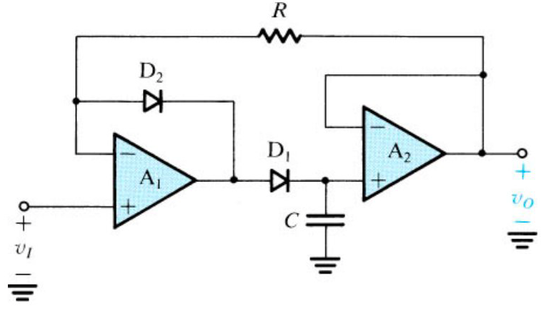
My guess is it is an active rectifier (no direct drop voltage loss) with peak detector.
Keys parts: 1) A diode (D1) rectifies, that is it allows to pass electrons in one direction e.g.: only positive voltage, but it has a drop voltage due to the junction direct voltage 2) Something in the feedback in the minus (-) input of an opamp (A1) is magically compensated by the gain ot the opamp, here the direct drop voltage is compensated. 3) Peak detector is made by diode D1 and the capacitor C, capacitor is like a tank you can fill with electrons. 4) A2 works as a isolation buffer, it allows low impedance charges to not affect to the discharge of the capacitor C, it is only discharged by the high impedance input of the opamp.
Let me know if I am wrong!
posted by 21 Feb 2016Hey Manel,
Thanks for the explanation, helped a lot! I actually do know how capacitors, resistors, and diodes work, my problem is with the amp op and with the peak detector, also with putting diodes with a ampop, it cofunses me.
Thanks,
Thiago.
posted by 21 Feb 2016Hi Thiago and Manel, What Manel has posted is right. This video might help you understand what exactly is happening.http://youtu.be/jllsqRWhjGM I don't think the code is exactly what I want. The Peak detector detects the peak of the amplitude of a signal. But doesn't depend on the frequency ( I think!).
posted by 22 Feb 2016Hey Anitta,
Thanks for the link, this guy explains very well! I edit the answer a little. I believe it look mor like what you wanted now, but I am not sure... Please comment here if it is not. What kind of LCD are you using? Do you have code that you started to write? We could have a look, maybe we can help more...
posted by 22 Feb 2016With the added control of the reset transistor to Thiago's code. I'm assuming that you want to loop around resetting, waiting for a short period and then taking a reading.
I've also added some code to convert from ADC reading to voltage, 3.2 should be about the right scale factor but you may need to make some measurements and change that a little if you want it to be accurate. I've also added some code to output to the virtual serial port so that you can see the values on a PC. Handy for troubleshooting.
Serial pc(USBTX,USBRX);
DigitalOut myled(LED1);
DigitalOut resetFET (p21);
AnalogIn ain(p15);

//Declare LCD class here

int main() {

    resetFET = 1;
    uint32_t actualAnalogValue = 0;

    while(1){
       wait(0.01); // give it time to fully drain the capacitor. (will depend on component values)
       resetFET = 0; // disable the reset FET

        /*Waits for the signal in the output of the peak detector to stabilize*/
        wait(1);  // should be a couple of times your expected input frequency of interest.

        /*Reads the value in the output of the peak detector*/
        actualAnalogValue = ain.read_u16();

        resetFET = 1; // start the reset now

        /* convert to a voltage by multiplying by 3.2 and dividing by 2^16. */
        float voltage = actualAnalogValue * 3.2 / (1<<16);
        pc.printf("Peak is %.2f\r\n", voltage);

        /*Displays it on the LCD Monitor*/
        //here

        }
}
I've assumed that you have an n channel FET from the capacitor to ground so a high on the gate will turn it on and reset the peak. Make sure you put a resistor in series with the FET otherwise you're effectively shorting the op-amp output to ground which isn't good for the parts. Small values will reset quicker but put more of a strain on the parts.
I've included a short wait at the start of the while loop to give time for the reset to take place. Depending on the components used the time taken to output to the display may introduce a long enough delay that you don't need that extra wait in there.
posted by 22 Feb 2016
Hi Andy and Thiago, Thank you for your help! I think Andy's code looks like what I was thinking. I will certainly try it out and tell you about my results. I think I didnt make myself clear as to what kind of display I will be using! It is a group project and my group mate is developing a 12x12 matrix LED display to show the results of my circuit. Both parts will be connected using SPI protocol.
posted by Annita Panagi 24 Feb 2016