Important changes to forums and questions
All forums and questions are now archived. To start a new conversation or read the latest updates go to forums.mbed.com.
9 years, 11 months ago.
F446RE via 3.3V battery
Hey guys
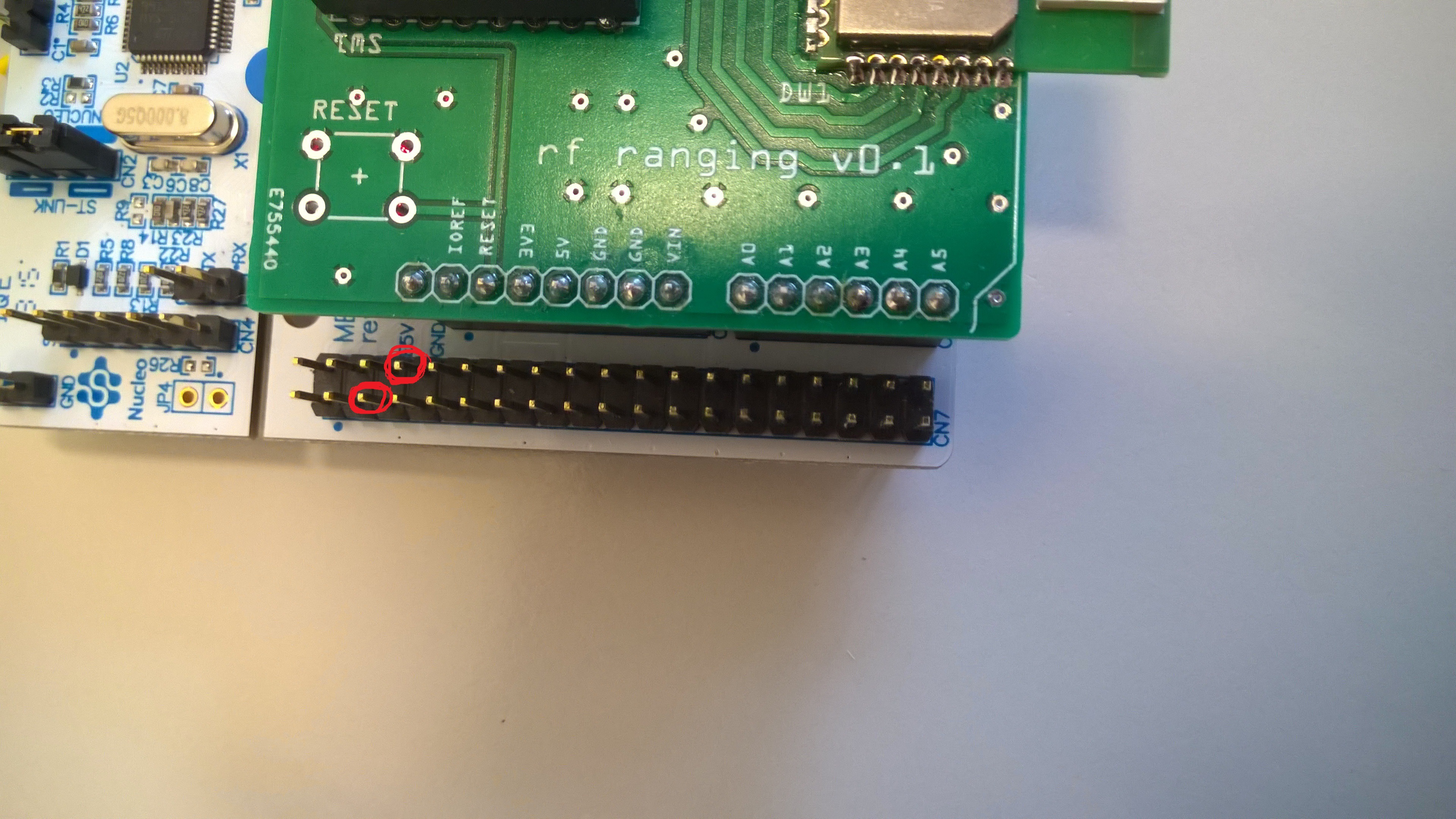
I have received my 3.3V batteries that I want to attach to my Nucleo Boards so that I don't have to wear the cable around all the time. So i attached the battery to the CN7 15 pin but it didn't work. Also i tried out the 5V and some other pins but none of them resulted in a working setup. Even worse I think I broke a board(there were some sparks at a moment).
Now I don't dare to continue without being sure to do it the right way.
Where exactly do I have to attach the battery to the board?
Thanks
nj

2 Answers
9 years, 11 months ago.
Pin3 (+3.3v) and Pin8 (GND) on the 'morpho' connectors is correct, however check the battery voltage, AFAIK a 3.3v battery does not exist unless it is a coin cell type, these won't power your board for very long.
If you have connected a Li-Ion cell, that will normally be 4.2v when charged so will probably kill your MCU and/or your 3.3v regulator U4. You must remove JP6 when connecting external 3.3v VDD and this must be regulated. Just using a battery even if 3.3v is not really good enough. You can use the 3.3V regulator U4 with a battery of 3.5v to 5v by connecting the +ve battery terminal to one of the pins of JP6. That must be on the VDD pin. You can make a continuity check between the JP6 pin and pin3 on the 'morpho' connectors.
What exactly is 'smoking' ? Remove JP6 link and power the board via the ST-Link USB connection. If no smoke and the Interface LED LD1 lights normally, then measure the voltage on the JP6 +3.3v pin. If that reads 3.3v then the ST-Link and VDD regulator is working. Then you can measure the MCU current briefly across the JP6 pins. If around 20mA all is correct and should not smoke.
If you do not have 3.3v on the JP6 +3.3v pin and/or smoke, then possibly the 3.3v regulator U4 has been damaged.
 I forgot to remove the Jumper :S, must have been that..
It is correct that I have 3.7V LiPo batteries, but not precisely 3.3V. Do you think it's better to put them on the 3.3V or the 5V pins?
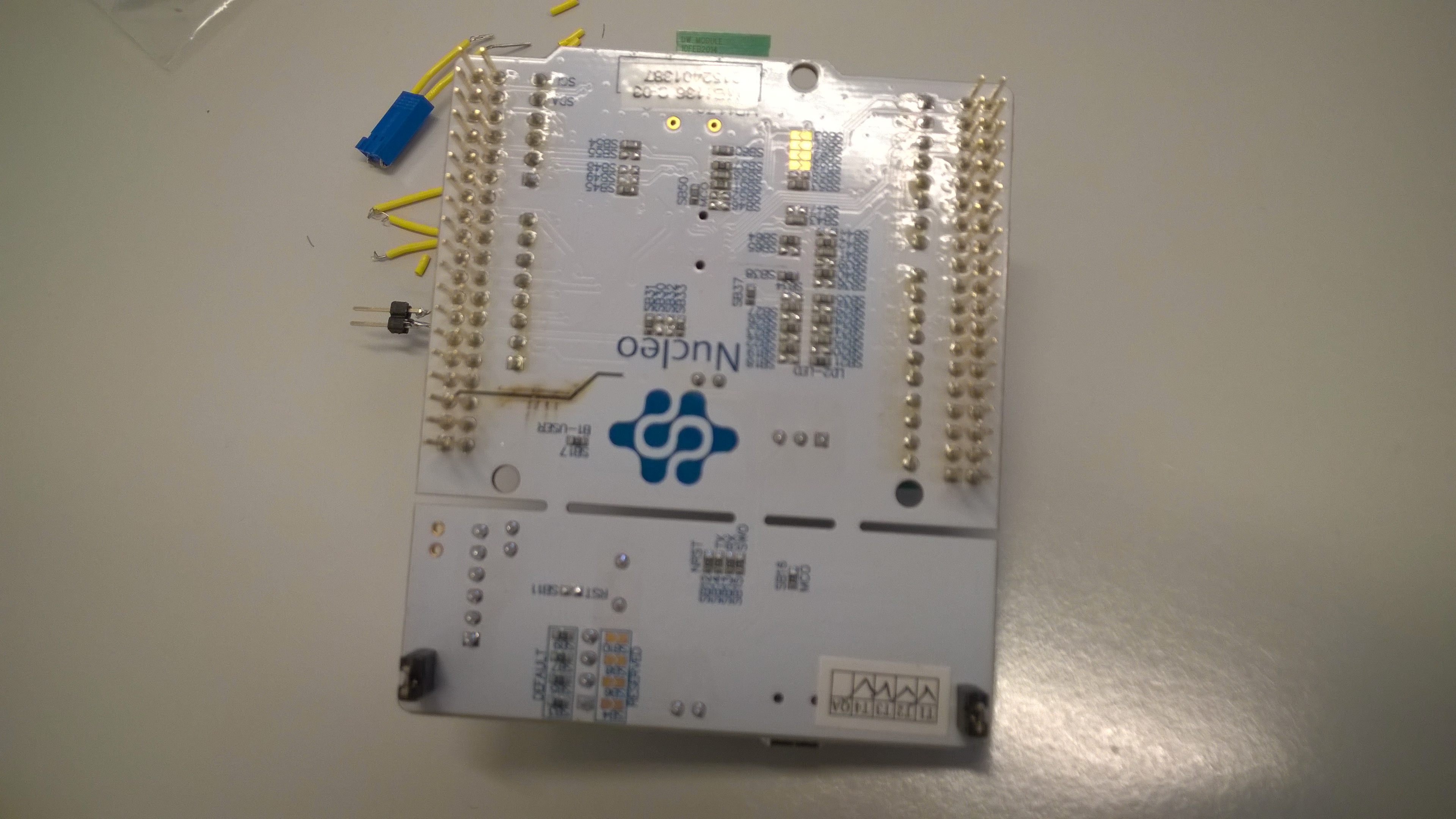
I added a picture of the "smoked" part.. for your entertainment and for proving that I am really that stupid ;)
posted by 09 Feb 2016Not stupid, learning curve. No problem, you MUST use the Li-Po battery on the 5V pin, the LDO regulator will work until the cell voltage reaches about 3.4v then there will be no voltage regulation but will continue to power the MCU. Li-Po's terminal voltage is around 4.85v when fully charged. Also you do not want to discharge the Li-Po below 3v as this causes problems with the battery's chemistry and will reduce its capacity. These Li-Po batteries are 'dangerous', they have extremely low internal resistance so will punch out high amps if shorted, hence the burnt track. I would be inclined to add a fuse inline, 500mA will do unless you are driving a high current circuit, in which case add a second fuse higher rating fuse for that circuit. Saves frying PCB track :)
posted by 09 Feb 20169 years, 11 months ago.
Look at [https://developer.mbed.org/platforms/ST-Nucleo-F446RE/] : the pin is clearly visible.
But you have to look at the user manual of the Nucleo (link is in the Technical references) to know the limitations.