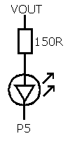
I have a related problem. If I connect an ordinary red LED in series with a 150 ohm resistor and connect it between VOUT and P5 like this :

then I can turn it in and off by configuring P5 as an output and toggling it. When P5 is low the LED lights, when high it turns on, although it does seem a little dull. I assumed that the voltage drop across the LED would be around 2V and was aiming for a current of 10 mA. If VOUT is 3.3V then there should be 1.3V across the resistor and so I should get 8.67 mA with a 150 ohm resistor.
However, when I tried it, what I got was 1.00 V across the resistor, 1.95V across the LED and a current of 5.97 mA. This doesn't make sense. If I have 1V across a 150 ohm resistor then I should have a current of 6.67 mA. More worrying is the fact that the VOUT voltage has dropped from 3.3V to 2.95V. How can this be? The regulator (IC4) should be able to cope with 10 mA.
Or can it? On further investigation I discovered that the voltage in the VU pin (USB supply, pin 39, should be 5V) is actually only 4.81V. This voltage is fed to the input of the regulator (IC4) via a BAT60A diode (D1) and I reckon if the mbed is drawing 200 mA (worst case, I am using the Ethernet hardware) then I could get a voltage drop of between 0.2V and 0.3V, which means the regulator is only being supplied with 4.51V. Since the regulator has a dropout voltage of around 1V this should still be enough, although the electrical characteristics on the regulator's datasheet all use test voltages high than that I'm not entirely sure.
Has anyone else had similar problems?
Would I be better off using an external 5V supply connected across pins 1 (GND) and 2 (VIN)?
Has anyone else noticed such a low USB voltage on their PC?
Hello,
Does anybody know how much current the Vout pin (3.3Vdc regulated) can supply?
I can't find this info anywhere on the site.
Maybee i can see what power chip is used in the schematic and find out but maybee someone here knows.
/Mateo