production board / ISP FTDI / Other I/O pin of LPC

24 Aug 2010

Hi,

I start to work on my own board to match my need, i would like to use mbed to build my program and download the bin (after bin2hex) to my board.

Thanks to Martin for is great help !

- On my own board i need more I/O than mBed, i would like to access to P0.20 and P0.21 (for example) of the LPC , how to access to other LPC1768 i/o with mBed compiler ?

- Are you already try an FTDI 232 (Usb/Serial bridge) conected to the TXD0 and RXD0,  DTR to /Reset (pin 17) and RTS to /ISP (P2.10 / pin 53) to access to the ISP with flashmagic  ?

Something like this could be work with LPC1768 ?


Thank you,

Chris

24 Aug 2010

Hi Chris

You can use my notebook for pinout of the LPC1768

LPC1768 Pin functions

In the program you can add this .c file,

/*    Platform header file,
*    for prototype boards
*    with LPC1768
*    Defines pin connections
*/

#pragma once
#ifdef PROTOPLATFORM             // #define PROTOPLATFORM - in main.c to use these pinnames

//Internal Pins PORT_0
#define P0_0 (P0_0)              // Pin 46 - LPC1768
#define P0_1 (P0_1)              // Pin 47 - LPC1768
#define P0_2 (P0_2)              // Pin 98 - LPC1768
#define P0_3 (P0_3)              // Pin 99 - LPC1768
#define P0_4 (P0_4)              // Pin 81 - LPC1768
#define P0_5 (P0_5)              // Pin 80 - LPC1768
#define P0_6 (P0_6)              // Pin 79 - LPC1768
#define P0_7 (P0_7)              // Pin 78 - LPC1768
#define P0_8 (P0_8)              // Pin 77 - LPC1768
#define P0_9 (P0_9)              // Pin 76 - LPC1768
#define P0_10 (P0_10)            // Pin 48 - LPC1768
#define P0_11 (P0_11)            // Pin 49 - LPC1768
#define P0_15 (P0_15)            // Pin 62 - LPC1768
#define P0_16 (P0_16)            // Pin 63 - LPC1768
#define P0_17 (P0_17)            // Pin 61 - LPC1768
#define P0_18 (P0_18)            // Pin 60 - LPC1768
#define P0_19 (P0_19)            // Pin 59 - LPC1768
#define P0_20 (P0_20)            // Pin 58 - LPC1768
#define P0_21 (P0_21)            // Pin 57 - LPC1768
#define P0_22 (P0_22)            // Pin 56 - LPC1768
#define P0_23 (P0_23)            // Pin 09 - LPC1768
#define P0_24 (P0_24)            // Pin 08 - LPC1768
#define P0_25 (P0_25)            // Pin 07 - LPC1768
#define P0_26 (P0_26)            // Pin 06 - LPC1768
#define P0_27 (P0_27)            // Pin 25 - LPC1768
#define P0_28 (P0_28)            // Pin 24 - LPC1768
#define P0_29 (P0_29)            // Pin 29 - LPC1768
#define P0_30 (P0_30)            // Pin 47 - LPC1768

//Internal Pins PORT_1
#define P1_0 (P1_0)              // Pin 95 - LPC1768
#define P1_1 (P1_1)              // Pin 94 - LPC1768
#define P1_4 (P1_4)              // Pin 93 - LPC1768
#define P1_8 (P1_8)              // Pin 92 - LPC1768
#define P1_9 (P1_9)              // Pin 91 - LPC1768
#define P1_10 (P1_10)            // Pin 90 - LPC1768
#define P1_14 (P1_14)            // Pin 89 - LPC1768
#define P1_15 (P1_15)            // Pin 88 - LPC1768
#define P1_16 (P1_16)            // Pin 87 - LPC1768
#define P1_17 (P1_17)            // Pin 86 - LPC1768
#define P1_18 (P1_18)            // Pin 32 - LPC1768
#define P1_19 (P1_19)            // Pin 33 - LPC1768
#define P1_20 (P1_20)            // Pin 34 - LPC1768
#define P1_21 (P1_21)            // Pin 35 - LPC1768
#define P1_22 (P1_22)            // Pin 36 - LPC1768
#define P1_23 (P1_23)            // Pin 37 - LPC1768
#define P1_24 (P1_24)            // Pin 38 - LPC1768
#define P1_25 (P1_25)            // Pin 39 - LPC1768
#define P1_26 (P1_26)            // Pin 40 - LPC1768
#define P1_27 (P1_27)            // Pin 43 - LPC1768
#define P1_28 (P1_28)            // Pin 44 - LPC1768
#define P1_29 (P1_29)            // Pin 45 - LPC1768
#define P1_30 (P1_30)            // Pin 21 - LPC1768
#define P1_31 (P1_31)            // Pin 23 - LPC1768

//Internal Pins PORT_2
#define P2_0 (P2_0)              // Pin 75 - LPC1768
#define P2_1 (P2_1)              // Pin 74 - LPC1768
#define P2_2 (P2_2)              // Pin 73 - LPC1768
#define P2_3 (P2_3)              // Pin 70 - LPC1768
#define P2_4 (P2_4)              // Pin 69 - LPC1768
#define P2_5 (P2_5)              // Pin 68 - LPC1768
#define P2_6 (P2_6)              // Pin 67 - LPC1768
#define P2_7 (P2_7)              // Pin 66 - LPC1768
#define P2_8 (P2_8)              // Pin 65 - LPC1768
#define P2_9 (P2_9)              // Pin 64 - LPC1768
#define P2_10 (P2_10)            // Pin 53 - LPC1768
#define P2_11 (P2_11)            // Pin 52 - LPC1768
#define P2_12 (P2_12)            // Pin 51 - LPC1768
#define P2_13 (P2_13)            // Pin 50 - LPC1768

//Internal Pins PORT_3
#define P3_25 (P3_25)            // Pin 27 - LPC1768
#define P3_26 (P3_26)            // Pin 26 - LPC1768

//Internal Pins PORT_4
#define P4_28 (P4_28)            // Pin 82 - LPC1768
#define P4_29 (P4_29)            // Pin 85 - LPC1768

#endif
So when you #define PROTOPLATFORM in main.c, it uses the names of this file.

Now all there is to do is program the pins you'd like to use, and compile.


/ Lerche

24 Aug 2010 . Edited: 24 Aug 2010

Hi Chris's (Hmm... everyone on this thread is Chris)

I;ve recently added FTDI header and JTAG headers to the reference design :

http://mbed.org/cookbook/Reference-Design

Also, My notebook page covers ome of the issues you might face in bringing up your own PCB.

http://mbed.org/users/chris/notebook/prototype-to-hardware

Hope that helps.. shout if any of that should be revised/improved


Cheers,
Chris


24 Aug 2010

Hi Chris and Chris ;-)

Chris, thank you for your "pins connection defines" ! really nice and very useful for my project.

Chris, thank you too for the reference design !

Only RXD0 and TXD0 with ISP to ground to enter in ISP mode -> really great news

Chris... i have a question : could your really sold the 83848J with hand soldering with ease ? i have not an reflow oven (for the moment).

Thank you again Chris and Chris.

Chris ;-)

24 Aug 2010

Hi Chris,

Hmmm.. I havent actually tried to solder a DP83848J, but if I were doing it i'd use solder paste and a hot air gun. I use a hot air gun to reflow LPC1768s, mainly to remove them from PCBs, but i'd be fairly confident that with a little time and care, it should be possible. Of course, you could always switch to the DP83848C (as used on the original LPC2368 mbed). This is basically the same part, but in a TQFP package, might be easier than the QFN package of the "J" variant.

Hope that helps,

Chris


25 Aug 2010

Hi Chris,

Sorry to hi-jack the thread (temporarily) but it is kind-of related - please feel free to make it into a different thread if that's more suitable!

Are there any other PHY devices that will be supported by the current libraries? If I understood the schematics correctly, you're using the RMII interface so would any other RMII-compliant PHY be suitable?

Or do we need to stick with the Nat Semi device?

We use a Micrel PHY (KSZ8041) on our other LPC2xxx boards and I was hoping that this may be an option for our own LPC176x-based board design (just starting to prototype parts of it with mbed before going to a custom board).

If there are other know options, can these be listed somewhere please? I know it's not a major goal to support other boards at the moment, but it would help to make a very useful development tool even better!

Any info would be most helpful!

Cheers,

    JezC

25 Aug 2010 . Edited: 25 Aug 2010


user avatar Chris Styles wrote:

Hi Chris,

Hmmm.. I havent actually tried to solder a DP83848J, but if I were doing it i'd use solder paste and a hot air gun. I use a hot air gun to reflow LPC1768s, mainly to remove them from PCBs, but i'd be fairly confident that with a little time and care, it should be possible. Of course, you could always switch to the DP83848C (as used on the original LPC2368 mbed). This is basically the same part, but in a TQFP package, might be easier than the QFN package of the "J" variant.

Hope that helps,

Chris


Hi Chris,


I will update my eagle file to the DP83848C version, thank you for the tips.

TQFP are easy to sold with hand soldering and flux, but i think to buy a pro tool to sold compoment now...

Thank you !

Chris.

25 Aug 2010

Hi Chris,

I just modify your lbr and sch to add the DP83848C device (LQFP-48) and switch from the "J" to "C" version on my eagle scheme, connect an RJ45 connector with built-in transformers and leds (MagJack from Sparkfun lbr).

I need to add signals on the "C" Version : Power_Down (pin 7), RESERVED@6 (pin 20), RESERVED@7 (pin 21), 25Mhz_Out (pin 25), Led_Act (pin 26), IOGND@1 (pin 35).

I try to place new signals to limit the differences beetween the "C" and "J" version.

I could send to you the modified lbr and the .sch, it's an un tested design for the moment, but i hope to start the routing off all my board next week-end ! Hope the "C" version work exactly like the "J" version...

About Leds, why leds signals are routed to the LPC1768 ? mBed use them to check something ? how-to use leds on my RJ45 plug too ? (sorry i'm a mBed rookie).
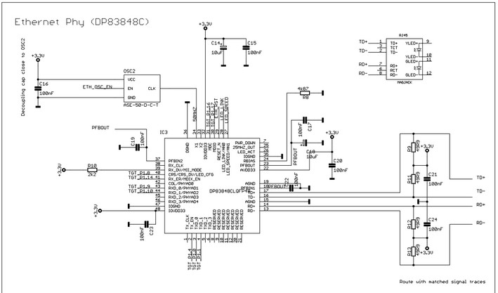
Chris (the "frenchie").

29 Jan 2011

Hello Chris Styles and Chris The Frog and all other Chris.

Im another Chris (Chris Cuebler from Hungary) :)

I build an own board, and i tryed using DP83848VV (Have JTAG), and the PHY is not work. When i download a sample program with eth specific headers (libs), the software is maybe freez in eth init because the first program code in mian is a serial fprint and that is not received.

the significant difference between C and I version of PHY only the JTAG port, and the power down pin (pin 6..12). (all JTAG pin is disconnected in the board)

can you help me?

thanks..

ps.: Sorry for my hungaryan english.... i still a developing..