Adafruit Bluefruit LE UART Friend
Bluetooth Low Energy (BLE) module
Hello World
Import programSerialPassthrough_LPC1768
Serial pass through program - version for mbed LPC1768 pins 28,27 9600 baud
Last commit 16 Sep 2015 by  jim hamblen
Library
Import programSerialPassthrough_LPC1768
Serial pass through program - version for mbed LPC1768 pins 28,27 9600 baud
Last commit 16 Sep 2015 by jim hamblen
Datasheet
https://learn.adafruit.com/introducing-the-adafruit-bluefruit-le-uart-friendNotes

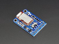
Adafruit Bluefruit LE UART Friend
The low cost Adafruit Bluefruit BLE board features an ARM Cortex M0 core running at 16MHz with 256KB flash memory and 32KB SRAM. Peak current draw is <20mA (radio actively transmitting/receiving) Transport is a UART @ 9600 baud with HW flow control (CTS+RTS). It has on-board 3.3V voltage regulation and a Bootloader with support for safe OTA firmware updates. A UART mode or easy AT command set can be used (note switch on board above). A Free demo app along with source code is available for iOS or Android phones or tablets. The app supports over the air firmware updates, UART text transfers, user control pads, and IMU or GPS data streaming from the phone or tablet. If serial port UARTs are not available, the device is also available in a different version with SPI.
Wiring for Hello World BLE UART Demo
Here are the pins to hookup for the mbed LPC1768
| mbed | Adafruit BLE |
|---|---|
| gnd | gnd |
| VU(5v) | Vin (3.3-16VDC) |
| nc | RTS |
| Gnd | CTS |
| p27 (Serial RX) | TXO |
| p28 (Serial TX) | RXI |
Hello World BLE UART demo
Here are the steps for the demo:
Mini slide switch on Adafruit board set to "UART" (not "CMD")
Download the free "Adafruit Bluefruit BLE" App for your iOS or Android phone or tablet from the Apple App or Google Play store. (First time only!)
Compile and Download the serial pass through program below to your mbed. It transfers data from the serial port connected to the BLE module to mbed's USB Virtual Com port. A PC terminal window connected to mbed's USB Virtual Com port then allows the user to see the data from the BLE module or send data from the PCs keyboard.
Import programSerialPassthrough_LPC1768
Serial pass through program - version for mbed LPC1768 pins 28,27 9600 baud
Last commit 16 Sep 2015 by jim hamblen
Reset the mbed to run the serial pass through program
Start a terminal application program on your PC at 9600 baud and connect to mbed's USB virtual com port
Red power/status LED should blink on Adafruit board
After installing, find and start the "Adafruit Bluefruit BLE" App on your phone
After scanning stops on the phone app, Connect to "Adafruit Bluefruit BLE"
If prompted for a device firmware update, go ahead and update the firmware. This works over the air using the Bluetooth RF link.
Select "UART" mode on phone window that appears
When connected, blue LED on Adafruit board should turn on
Anything typed in the phone's UART text window, will be sent via bluetooth after hitting "send" and appear in the PCs terminal window as seen below.

Any characters typed in the PC's terminal window will appear in the phone's text window as seen below.

LED and Control Pad Demo
Once it is connecting and transfers text, try this demo. The program below decodes button messages from the number keys on the right side of the control pad. Hitting a button sends a text message like "!B11" (button 1 hit) or "!B20" (button 2 released).
#include "mbed.h"
BusOut myled(LED1,LED2,LED3,LED4);
Serial blue(p28,p27);
int main()
{
    char bnum=0;
    while(1) {
        if (blue.getc()=='!') {
            if (blue.getc()=='B') { //button data
                bnum = blue.getc(); //button number
                if ((bnum>='1')&&(bnum<='4')) //is a number button 1..4
                    myled[bnum-'1']=blue.getc()-'0'; //turn on/off that num LED
            }
        }
    }
}
Compile and download it to mbed and reset.

After connecting to the module, instead of "UART" select "Controller" then "Control Pad". Each number key will turn on one of the four built-in LEDs on the mbed LPC1768, and when the button is released it turns off the LED.
Once more keys need to be decoded for controlling something a little more complex such as a robot or game, a switch statement can be added. A template is provided in the code below.
#include "mbed.h"
BusOut myled(LED1,LED2,LED3,LED4);
Serial blue(p28,p27);
int main()
{
    char bnum=0;
    char bhit=0;
    while(1) {
        if (blue.getc()=='!') {
            if (blue.getc()=='B') { //button data packet
                bnum = blue.getc(); //button number
                bhit = blue.getc(); //1=hit, 0=release
                if (blue.getc()==char(~('!' + 'B' + bnum + bhit))) { //checksum OK?
                    myled = bnum - '0'; //current button number will appear on LEDs
                    switch (bnum) {
                        case '1': //number button 1
                            if (bhit=='1') {
                                //add hit code here
                            } else {
                                //add release code here
                            }
                            break;
                        case '2': //number button 2
                            if (bhit=='1') {
                                //add hit code here
                            } else {
                                //add release code here
                            }
                            break;
                        case '3': //number button 3
                            if (bhit=='1') {
                                //add hit code here
                            } else {
                                //add release code here
                            }
                            break;
                        case '4': //number button 4
                            if (bhit=='1') {
                                //add hit code here
                            } else {
                                //add release code here
                            }
                            break;
                        case '5': //button 5 up arrow
                            if (bhit=='1') {
                                //add hit code here
                            } else {
                                //add release code here
                            }
                            break;
                        case '6': //button 6 down arrow
                            if (bhit=='1') {
                                //add hit code here
                            } else {
                                //add release code here
                            }
                            break;
                        case '7': //button 7 left arrow
                            if (bhit=='1') {
                                //add hit code here
                            } else {
                                //add release code here
                            }
                            break;
                        case '8': //button 8 right arrow
                            if (bhit=='1') {
                                //add hit code here
                            } else {
                                //add release code here
                            }
                            break;
                        default:
                            break;
                    }
                }
            }
        }
    }
}
In this example, additional code was added to check the checksum byte sent at the end of each key event text string. In case of a checksum error, the command is ignored.
Using Serial Interrupts
Some applications may need to do additional tasks while waiting for a new button message. Getc() does not return until a new character is sent, so most of the processor time is spent waiting for new characters to arrive. Serial receive character interrupts can be used to parse each button message. The main program can then do other tasks and periodically check to see if a new message has been received.
The example code below shows how to process button messages using interrupts. Main checks for a new button message each time through the while loop. In this example, the while loop in main blinks led1 and button 4 controls led4. It is still possible to miss a button message, if main does not check back for messages often enough.
#include "mbed.h"
Serial Blue(p28,p27);
DigitalOut myled(LED1);
DigitalOut myled4(LED4);

//global variables for main and interrupt routine
volatile bool button_ready = 0;
volatile int  bnum = 0;
volatile int  bhit  ;
//state used to remember previous characters read in a button message
enum statetype {start = 0, got_exclm, got_B, got_num, got_hit};
statetype state = start;
//Interrupt routine to parse message with one new character per serial RX interrupt
void parse_message()
{
    switch (state) {
        case start:
            if (Blue.getc()=='!') state = got_exclm;
            else state = start;
            break;
        case got_exclm:
            if (Blue.getc() == 'B') state = got_B;
            else state = start;
            break;
        case got_B:
            bnum = Blue.getc();
            state = got_num;
            break;
        case got_num:
            bhit = Blue.getc();
            state = got_hit;
            break;
        case got_hit:
            if (Blue.getc() == char(~('!' + ' B' + bnum + bhit))) button_ready = 1;
            state = start;
            break;
        default:
            Blue.getc();
            state = start;
    }
}

int main()
{
//attach interrupt function for each new Bluetooth serial character
    Blue.attach(&parse_message,Serial::RxIrq);
    while(1) {
        //check for a new button message ready
        if(button_ready && (bnum=='4')) { // button 4 changed
            myled4 = bhit - '0'; //turn led4 on/off
            button_ready = 0; //reset flag after reading button message
        }
        //do other tasks in main - interrupts will process button message characters
        myled = 1;
        wait(0.1);
        myled = 0;
        wait(0.1);
    }
}
If the button action to be taken can be performed quickly with just a few lines of code it could be implemented directly in the interrupt routine instead of passing messages for main to check, but long execution times for interrupt routines need to be avoided since they can cause a multitude of other problems.
Color Picker RGB LED Demo
For this demo, select the color picker instead of the control pad

This demo code below reads in color packets from the app and sets the color of an RGB LED using three PWM pins. Select a color using the color wheel and hit send. The color wheel GUI is a bit different in the Android app. A Sparkfun RGB LED was used with three 100 ohm series resistors connected to PWM pins 21,22,23 (RGB) on the mbed LPC1768.

#include "mbed.h"

BusOut myled(LED1,LED2,LED3,LED4);
Serial bluemod(p28,p27);
PwmOut red(p21);
PwmOut green(p22);
PwmOut blue(p23);

int main()
{
    char bred=0;
    char bgreen=0;
    char bblue=0;
    red = green = blue = 0;
    while(1) {
        if (bluemod.getc()=='!') {
            if (bluemod.getc()=='C') { //color data packet
                bred = bluemod.getc(); // RGB color values
                bgreen = bluemod.getc();
                bblue = bluemod.getc();
                if (bluemod.getc()==char(~('!' + 'C' + bred + bgreen + bblue))) { //checksum OK?
                    red = bred/255.0; //send new color to RGB LED PWM outputs
                    green = bgreen/255.0;
                    blue = bblue/255.0;
                }
            }
        }
    }
}
GPS and IMU Data Streaming
The app's controller GUI also has an option to stream IMU or GPS data from the phone. Click the Location "off" button to "on" to start streaming the GPS location values to mbed.

The float values for x,y,z are transferred as four bytes over the serial link. The four bytes need to be packed back into a 32-bit float, to get the original float value. The code below shows a way to do this and it prints out the GPS data from the phone to mbed's USB virtual com port. This approach will also work for the IMU options.
#include "mbed.h"
Serial bluemod(p28,p27);

//C union can convert 4 chars to a float - puts them in same location in memory
//trick to pack the 4 bytes from Bluetooth serial port back into a 32-bit float
union f_or_char {
    float f;
    char  c[4];
};

int main()
{
    char bchecksum=0;
    char temp=0;
    union f_or_char x,y,z;
    while(1) {
        bchecksum=0;
        if (bluemod.getc()=='!') {
            if (bluemod.getc()=='L') { //GPS data packet
                for (int i=0; i<4; i++) {
                    temp = bluemod.getc();
                    x.c[i] = temp;
                    bchecksum = bchecksum + temp;
                }
                for (int i=0; i<4; i++) {
                    temp = bluemod.getc();
                    y.c[i] = temp;
                    bchecksum = bchecksum + temp;
                }
                for (int i=0; i<4; i++) {
                    temp = bluemod.getc();
                    z.c[i] = temp;
                    bchecksum = bchecksum + temp;
                }
                if (bluemod.getc()==char(~('!' + 'L' + bchecksum))) { //checksum OK?
                    printf("Latitude = %f  Longitude = %f  Altitude = %f\n\r",x.f, y.f, z.f);
                }
            }
        }
    }
}

If mbed starts dropping characters in packets in more complex applications, it might make sense to use the interrupt driven BufferedSerial (instead of Serial) and/or make a receive serial character data thread in the RTOS. If an application is running using threads in the RTOS, don’t forget that getc() blocks until a new character arrives and this will use a lot of processor time. Prior to calling getc(), using while(!readable()) to test first for a new character available and a yield or wait if not, will free up significant processor time for other threads.
Tilt Controller Demo
Here is a final demo using the phone or tablet as a tilt based controller. Download the demo code below, connect, select controller, and turn on Accelerometer data streaming. The code below reads accelerometer data packets. Using the X and Y acceleration values (range is -10.0 to 10.0), the code controls the four built in LEDs on the mbed LPC1768 using PWM (PWM can dim the LEDs with a 0.0 to 1.0 value).
#include "mbed.h"
Serial bluemod(p28,p27);
PwmOut left_led(LED1);
PwmOut right_led(LED4);
PwmOut forward_led(LED2);
PwmOut reverse_led(LED3);

//C union can convert 4 chars to a float - puts them in same location in memory
//trick to pack the 4 bytes from Bluetooth serial port back into a 32-bit float
union f_or_char {
    float f;
    char  c[4];
};

int main()
{
    char bchecksum=0;
    char temp=0;
    union f_or_char x,y,z;
    while(1) {
        bchecksum=0;
        if (bluemod.getc()=='!') {
            if (bluemod.getc()=='A') { //Accelerometer data packet
                for (int i=0; i<4; i++) {
                    temp = bluemod.getc();
                    x.c[i] = temp;
                    bchecksum = bchecksum + temp;
                }
                for (int i=0; i<4; i++) {
                    temp = bluemod.getc();
                    y.c[i] = temp;
                    bchecksum = bchecksum + temp;
                }
                for (int i=0; i<4; i++) {
                    temp = bluemod.getc();
                    z.c[i] = temp;
                    bchecksum = bchecksum + temp;
                }
                if (bluemod.getc()==char(~('!' + 'A' + bchecksum))) { //checksum OK?
                    //printf("X = %f  Y = %f  Z = %f\n\r",x.f, y.f, z.f);
                    right_led = left_led = forward_led = reverse_led = 0.0;
                    if (x.f<=0.0) right_led = -x.f/10.0;//Scale to 0.0 to 1.0 for PWM so /10.0
                    else left_led = x.f/10.0;
                    if (y.f<=0.0) forward_led = -y.f/10.0;
                    else reverse_led = y.f/10.0;
                }
            }
        }
    }
}
Hold the phone or tablet level. Note the accelerometer readings in the GUI. Most have a high Z axis reading when the device is horizontal (On my device Z was near 10.0 and X and Y should be low near zero). This is the gravity vector. If the device is not accelerating due to linear motion, the accelerometer detects the gravity vector.
When the phone or tablet is tilted, X or Y axis values increase and Z decreases (due to gravity vector). Using these values, the mbed code controls the brightness of the LEDs. LED1 indicates tilt left, LED4 is tilt right, LED2 is tilt forward, and LED3 is tilt reverse. The more the device is tilted, the brighter the corresponding tilt LED will become. If it is perfectly level, all LEDs are off.
Other OSes
A PC running Windows 10 with a (CSR chip) Bluetooth 4.0 dongle can detect and pair with the device, but it appears additional work or firmware is needed to get the UART services working and just have a regular com port appear in Windows for use by other programs. The Adafruit Bluefruit LE app and instructions found at https://github.com/adafruit/adafruit-bluefruit-le-desktop will allow it to work in Windows 10. Instructions can be found at Adafruit for Linux and OS X.
Command Mode
By placing the BLE UART Friend module in 'Command' mode (set the mode selection switch to CMD or setting the MODE pin to a high voltage) you can enter a variety of Hayes AT style commands to configure the device or retrieve basic information about the module or BLE connection. Commands include reducing RF power and turning off the MODE LED. There is documentation from Adafruit that explains the AT commands. There is also a data sheet for the board's RF/processor module at https://cdn-shop.adafruit.com/product-files/2267/MDBT40-P256R.pdf.
RPC Serial Using Bluetooth
The Remote Procedure Call (RPC) serial code examples could also be used to remotely control the mbed using the Bluetooth module, since the characters in commands wind up coming in on the serial port from the Bluetooth module. Interfacing-Using-RPC has more details. There are examples using both serial port polling and interrupt driven routines to handle remote procedure calls (RPC). An RPC tutorial is also available.

Tested boards
