SmartBoard WiFly
Information
This is a bridge board (aka 'shield') which supports the SparkFun WiFly module enabling remote sensing and remote control via WiFi.
Design Goals
Create a simple adapter to plug in the WiFly module, sacrificing the minimum number of usable circuits on the SmartBoard Baseboard. The WiFly can then be used as another communication channel for the SmartBoard.
Initial Concept
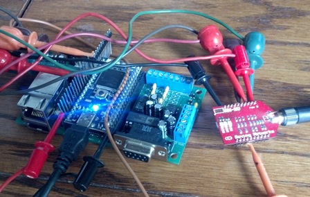
From the initial concept, I connected the WiFly as you see here. This was enough to prove the concept and develop a more "conventional" schematic.
Schematic
As you see this is mostly just providing an electrical interface.
PCB Design
The PCB is providing a stable mechanical as well as the electrical interface.
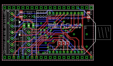
With the pin spacing of the SmartBoard WiFly, you can also use this module with a proto-board, but note that this will plug in on the outer row of sockets on the proto-board.
Order this PCB
BatchPCB is gone, and I haven't posted this elsewhere. Contact me to see if I have spares or am preparing an order.
BOM
And lastly, for a BOM, I had everything I needed laying around, so I didn’t create a BOM. I encourage you to double-check my notes here so you don’t get something you can’t use.
| Component | Description and a possible source |
|---|---|
| C1, C2 | 10 uF, 6v, SMD 1206 size. DigiKey 1276-1312-1-ND. |
| Wifly Header | 1 x 10 pos 2 MM Vert T/H (qty 2) Possibly these parts from DigiKey will work - S5751-10-ND, 3M9405-ND, 952-1354-5-ND |
| Mbed Header | 1 x 20 pos 2.54 MM Vert T/H 0.62 length (qty 2) It looks like I bought a few of these 50 pos parts and snapped them down to size - SAM1059-50-ND |
| Reset Sw | I had an old kit of switches I’ve been pilfering for years, and so used those. This is the DigiKey part - CKN1723-ND; I would have sourced a lower price unit if I didn’t already have this … |
| 3-pin Header | A106719-ND |
| Shunt | to use on the 3-pin header A26228-ND |
| Screw Terminals | There's a 7-position right angle ED2640-ND |
| Screw Terminals | And a 4-position 45 degree one that I never bought, so I do not have a part number |
Build this device
As simple as this is, you may want to skip this set of instructions, but at least scan them for details not to overlook.
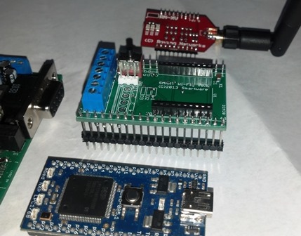 | SmartBoard baseboard just visible on the left, Smart WiFly in the middle, WiFly above that, and the mbed at the bottom. |
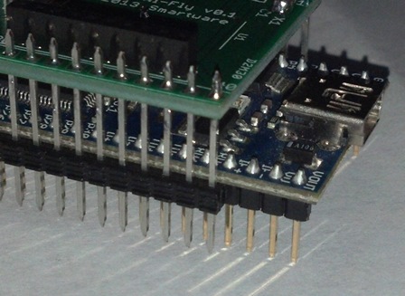 | Note how the mbed nestles between the leads of the Smart WiFly bridge board. When they are lined up together, the pair install easily into the baseboard. |
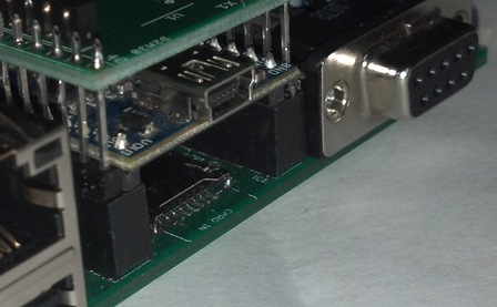 | Installed onto SmartBoard |
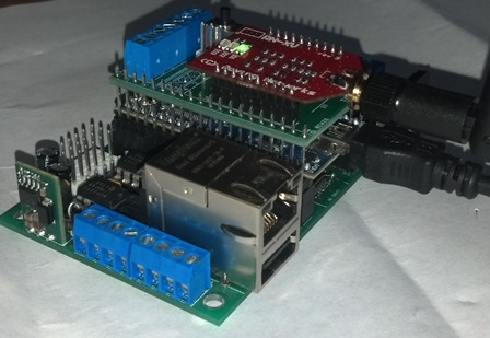 | Powered and Connected! |
Handy Tools:
- Fine tip soldering iron
- Small diameter solder
- A steady hand
- A good magnifier (an inexpensive eye loupe works well)
- A small bench vise to hold the PCB
Recommended Construction Sequence:
- The surface mount caps. I chose large footprint parts that are easier to hand solder. I recommend you place a little solder on the PCB pad, then remove most of it, then while holding the cap in place just touch each end to reheat the solder. Once it is attached, you can apply just a bit more solder as needed.
- Double-check that the caps are aligned on their pads.
- Install the socket strips for the WiFly. Just tack the corners, then check the alignment, then finish soldering them down.
- Install the stand-off connectors on the bottom side, so the top side of the PCB stands up tall (the long leads are sticking down below the board. If you do not seat the connector fully onto the board, it may be easier to perform that extra soldering step on pins 1, 10, and 20. Then repeat on 21, 30, and 40.
- On the top-side, the stand-off connector pins should be just barely stickup up above the PCB. Make sure they are of uniform height before you start soldering.
- Solder each of the pins on the top-side.
- Turn to the bottom side, and carefully heat and solder several, if not all, of the pins.
- Install the wire screw terminals. Note that there are two rows (one with 7 pins and the other with 4 pins).
- Unless you have a version that supports wire entry at 45 degrees, it will be difficult to use the inner connector, so you'll see I left it off of the build shown in the photos.
- Install the reset switch.
- Install the 3-pin header for the jumper.
Hardware Checkout
- Inspect the connections, then inspect them again. Look for good soldering quality, and no shorts to adjacent circuits.
- Checking continuity from pin to pin per the schematic. Check that the signals are not shorted to adjacent pins.
- Install the SmartBoard WiFly onto a suitable baseboard, but do not install the WiFly module.
- Power up and probe the WiFly strip socket pin 1 to ensure that it has only 3.3v, as anything higher might destroy the WiFly module.
- Power down and install the WiFly module.
- Test with the following program. For this program, you do need to refer to the WiFly User manual.
Software Checkout
Caution!
Many BaseBoards have some circuits permanently attached to the mbed modules pins. Check for conflicts with the WiFly module.
When using Smart WiFly v1.0 with SmartBoard v1.0, remove jumpers JP5, JP6, JP8, and JP10.
#include "mbed.h"

Serial pc(USBTX, USBRX);  // defaults to 9600 baud
Serial wifi(p28,p27);

int main() {
    pc.printf("Test Wifly!\r\n");

    while (1)
    {
        while(pc.readable())
            wifi.putc(pc.getc());
        while(wifi.readable())
            pc.putc(wifi.getc());
    }
}
At this stage, you can power up, run your favorite communications program on the PC and interact with the WiFly module. Start by typing "$$$" and look for the command prompt from the WiFly module. Long before this step, you should have downloaded the WiFly documentation. There's a lot to read there, but you can find good instructions to help you start up, connect to your [hopefully] secure network, and start experimenting.
What next ?
That's up to you, but you might be interested in the Smart WiFly WebServer.
9 comments on SmartBoard WiFly:
Please log in to post comments.

Wondering if you uploaded a board so we can order and build our own.