LPC812 LPCXpresso Board
Overview
The LPC812 is an ARM Cortex M0 (16K flash, 4K RAM, 30 Mhz) by NXP. A dedicated mbed enabled board is now available. The NXP LPC-800 MAX development board is compatible with LPCXpresso, mbed and Arduino. Target cost is $20 USD. More information is here, here and here. The mbed online compiler is now supporting the device and it is included as one of the mbed platforms.
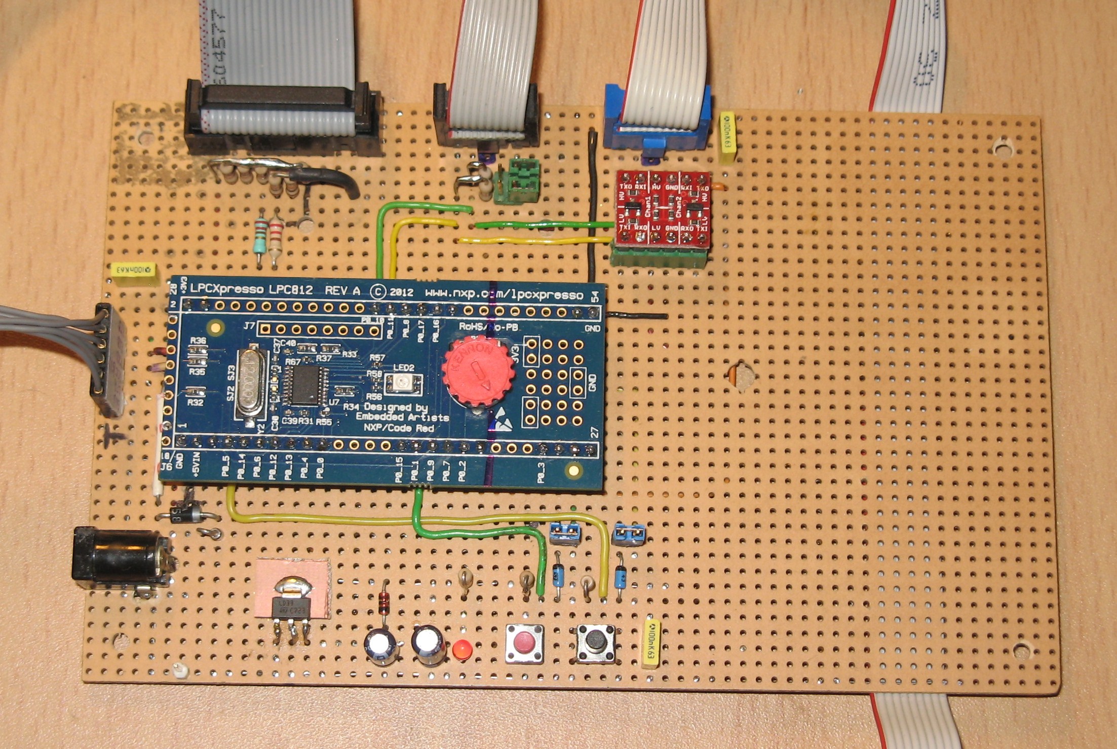
NXP and Embedded Artists have also released an LPC812 evaluation board (LPCXpresso LPC812). NXP were kind enough to give me an LPCXpresso LP812 for free at a trade show (thanks again!). The mbed online compiler may also be used with this board after some minor modifications and proper wiring. The picture below shows my test setup.

The board shows the 20pin JTAG/SWD connector (top left), the 6 pin USB-Serial and 5V power connector (left) and two I2C connectors, one of which has a Sparkfun 3V3 to 5V level converter.
Compatibility
The schematics for the LPC800 MAX board are now available and comparison with the LPCXpresso is possible. It is clear that the LPCXpresso does not have the mbed interface. All programming must done using ISP (serial) or through SWD. The LPC800 MAX supports a serial port to the host PC using the mbed interface. The mbed interface uses P0_1 (RX) and P0_6 (TX) for the PC host serial port to the LPC800 MAX. These pins are different from the default serial port as used by the LPCXpresso. That board uses default serial portpins RX (P0_0), TX (P0_4) and it needs a separate USB to serial converter. The same serial port and USB to serial converter are also used for ISP. Note that there is a design issue with the serial RX on the LPCXpresso: the pin is also connected to the trimming pot. This could interfere with the RX line when the pot is at the extreme ends of its range. I therefore used series resistors (330ohm) for TX and RX to the FTDI cable. That works fine. You cant see them in the pic above: they are hidden underneath the LPC812 board.
The USB to Serial converter that was used here has 3V3 voltage levels for TXD,RXD, DTR and RTS. It also provides 5V powersupply to the 3V3 voltage regulator on the carrierboard. The carrierboard provides pushbuttons for ISP mode and Reset. However, Flashmagic also supports automated activation of Reset and ISP through DTR and RTS. This feature is used here to avoid having to press the buttons manually. A couple of Schottky diodes are used to pull the ISP mode and Reset pins low using DTR and RTS.
The LPCXpresso board includes a dedicated SWD programming and debugging link. This link is supported by the LPCXpresso compiler (Code Red) and other tools. This proprietary interface has been physically cut from the LPC812 board shown above. It is possible to electrically disconnect the programming interface without actually cutting the board in half. The carrierboard features a standard 20pin JTAG/SWD connector that allows flashing and debugging using programmers like NXP LPC-Link or Segger J-Link. I also used series resistors for the SWD programmer (visible in the pic) to add some protection to the LPC812 portpins.
The LPC800 MAX supports analog conversion using a separate I2C ADC and DAC (PCF8591). You can find library for the PCF8591 here. The LPCXpresso does not have that feature. The LPC MAX also supports 8 additional digital I/O pins through an I2C portexander (PCA9672). The onboard RGB LED on LPC800 uses the same portpins as on the LPCXpresso board: P0_7 Red, P0_17 Green, P0_16 Blue.
The mbed lib default mode is to use the Internal RC oscillator (IRC) of the lpc812. You need patches only when you wish to use the external X-tal. Note that the LPC800 MAX board is wired to use the internal oscillator, you need to change some solder pads (SJ2, SJ3) when you want to activate the crystal. The LPCXpresso board on the other hand has the X-tal wired. Obviously, you loose some portpins (P0_8 and P0_9) when the X-tal is needed. The X-tal has the advantage of higher accuracy. Timers will have some error when the internal oscillator is used.
Note
Note that until around January 2015 the mbed lib did not use the PLL to run the LPC812 at its rated 30MHz clock. Instead it used the IRC to run at a clockspeed of only 12MHz. The fixed lib should be pushed soon to enjoy a factor 2.5 speed increase! You can also select the XTAL by making the appropriate selection in the file ''system_lpc81x.c" which is part of the CMSIS mbed library sourcecode.
The carrierboard shown above provides a 3V3 voltage regulator, some buffering capacitors and an indicator LED. Power may be provided through the USB-Serial converter or by a separate 5V supply. The LPCXpresso board has no onboard voltage regulator. You should supply it with 3V3. In my setup I use an FTDI that provides 5V supply and feed that to a regulator. Note that newer FTDI cables are available that provide 3V3 rather than 5V. Some offer a jumper or switch to select the voltage.
The I2C port is available on P0_10 (SDA) and P0_11(SCL). A Sparkfun 3V3 to 5 level converter allows I2C communication with 5V devices. The I2C port has been tested with a PCF8574 portexpander and a SAA1064 LED driver (see here), both devices seem to work as expected.
Note
Note that until around January 2015 the mbed lib I2C blockread and blockwrite methods were wrong. This leads to aborted communications. The fixed lib for block operations should be pushed soon. The I2C byte write and read operations were used as workaround although there are also issues with i2c.start() and the subsequent byte write of the slaveaddress. Any delay or interrupt between these two calls leads to unpredictable results.
Example Software
#include "mbed.h"

DigitalOut myled1(LED1);
DigitalOut myled2(LED2);

// Host PC Communication channels
//Serial pc(USBTX, USBRX); // tx, rx ===> Note default Pinnames USBTX and USBRX are wrong for LPCXpresso LPC812 !
Serial pc(P0_4, P0_0); // tx, rx

int main() {
    pc.printf("Hello World from LPC812\r\n");
    while(1) {
        myled1 = 0;
        wait(0.1);
        myled1 = 1;
        wait(0.9);

        myled2 = 0;
        wait(0.1);
        myled2 = 1;
        wait(0.9);

        pc.printf("*");
    }
}
Flashing Software
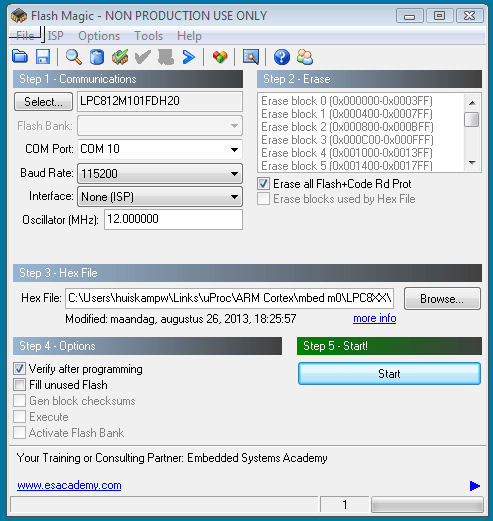
Compile the example software using the online mbed compiler after selecting LPC812 as target. This will result in a binary file (eg hello_lpc812.bin). Convert the binary file into a hex file using bin2hex utility. Note that a recent version of bin2hex is needed to avoid issues with bugs related to code size: bin2hex /4 hello_l8.bin hello_l8.hex Connect a USB to Serial converter (eg FTDI devices). Note my prototype used a converter based on PL2303. Install and run a recent version of (free) Flashmagic to program the device. Note that Flashmagic v7.50 and higher support the LPC800 family. Press ISP and Reset buttons (or wire DTR and RTS) to bring the LPC812 in ISP mode. Flash the code and it will start executing.

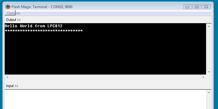
You may use the integrated Flashmagic terminal to observe serial output (default 9600 baud).

The alternative method for flashing the LPC812 is to use the SWD port. This requires a separate external programmer (eg NXPs LPC Link or J-Link).
First Results
The Hello World software runs. However, that small program takes up 11K, which is >60% of code space (auwch...). This is probably due to the relatively large mbed lib. User code size will hopefully grow at a modest rate. Some quick tests show that the Serial class and the printf() method are very expensive in codesize. Here are some figures for a small testprogram that uses Ticker and I2C objects:
| Serial object | Code Size |
|---|---|
| none | 3.4k (21%) |
| declared only | 8.3k (52%) |
| putc() used | 8.4k (52%) |
| printf() used | 11.8k (74%) |
This issue is known from other compilers also. In many cases a special small footprint version of printf has been developed to address this problem.
Note that the Pinnames.h file refers to the wrong USBTX and USBRX for the LPCXpresso board.
    // Serial to USB pins
    USBTX = P0_6,
    USBRX = P0_1,
The LPCXpresso needs
    // Serial to USB pins
    USBTX = P0_4,
    USBRX = P0_0,
The LPC812 supports several powerful features like a matrix switch for all pins and a capable statemachine controller. Still need to figure out how well that plays with mbed..
Warning
The LPC812 revision 4C has the ISP entry pin on PI00_12 (P0_12). A Low level on that pin during a hard reset or power-on reset will cause the device to enter the ISP bootmode where it expects to be flashed using the serial port rather than start normally. This issue will occur whenever you use P0_12 as DigitalIn (or even DigitalOut) pin that could be at a Low level during a reset. On the LPC800-MAX board this pin is also used as SPI SCK in ''SPI Slave'' mode and this use-case resulted in the problem described here.
References
20 comments on LPC812 LPCXpresso Board:
Please log in to post comments.

What did you do to get MBED to compile for LPC812 ?
I cannot get the compiler to work for my shiny new LPC-800-MAX board :(
Cheers
Ceri