3D Inverse Kinematics
3D Inverse Kinematics
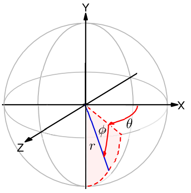
So on my notebook page Inverse Kinematics I showed how it's possible to calculate the joint angles of a simple 2 jointed leg from the desired foot position. The next step for the leg (pardon the pun!) is to add a second degree of freedom to the hip joint to allow the leg to move outwards from the body - kinda like Da Vinci's Vitruvian Man. This will give the coordinate systems similar to the one shown below:

More Maths
The procedure I will use to find the leg angles is in four parts.
First I'll find the angle of the that the leg protrudes from the body - i.e. the angle of ϒ relative to the XY plane. This can be calculated using, Angle = Tan-1 Z/Y. This will define the plane that the leg is confined to.
The second bit is to find how long the leg must be, given by the equation, L = √(X^2 + Y^2 + Z^2).
Third part - find the knee angle. In the same manner used for 2D Inverse Kinematics, because the lengths of all 3 sides of the triangle formed from the hip, knee and foot are known I can use the Law of cosines to calculate the the angle of the knee, i.e. Θ = Cos-1 (Femur^2 + Tibia^2 - L^2)/(2*Femur*Tibia).
Finally the Hip angle must be found. Again α is next found using same equation, which now becomes Θ = Cos-1 (Femur^2 + L^2 - Tibia^2)/(2*Femur*L), then β is calculated using trigonometry, i.e. β = Tan-1 X/Y, making the hip angle (which will be in a CCW direction this time!) 180° + α + β.
So that should allow me to find the angles that I need using any given X,Y,Z coordinates. So I'll move onto the code...
The Code
Once again I wrote a small test program to give the angles of the hip and knee under certain test positions. The code is shown below...
#include "mbed.h"

#define FEMUR 100
#define TIBIA 100
#define Y 100
#define PI 3.1415926

Serial pc(USBTX, USBRX);

int main() {
    pc.printf("\n\rTesting Started...\n");

    int x[] = {-100,100,100,-100};
    int z[] = {-100,-100,100,100};

    for (int i = 0;i<4;i++) {

        int X = x[i];
        int Z = z[i];

// Start by working out the angle to the XY plane
        float XYAngle = Z/Y;
        XYAngle = atan(XYAngle);

// Then find out the length of the leg L
        float L = (X*X) + (Y*Y) + (Z*Z);
        L = sqrt(L);

// Work out the Knee angle
        float Knee = (FEMUR*FEMUR)+(TIBIA*TIBIA)-(L*L);
        Knee = Knee / (2*FEMUR*TIBIA);
        Knee = acos(Knee);

// Work out Alpha
        float Alpha = (FEMUR*FEMUR)+(L*L)-(TIBIA*TIBIA);
        Alpha = Alpha / (2*FEMUR*L);
        Alpha = acos(Alpha);

// Work out Beta
        float Beta = (float) X/(float) Y;
        Beta = atan(Beta);

// Finally work out the Hip angle
        float Hip = PI + Alpha + Beta;

// Convert the angles to degrees...
        XYAngle = XYAngle * 180 / PI;
        Knee = Knee * 180 / PI;
        Hip = Hip * 180 / PI;

// Print the answers to terminal
        pc.printf("\n\rX = %d, Y = %d, Z = %d, XY Angle = %.2f, Hip = %.2f, Knee = %.2f",X,Y,Z,XYAngle,Hip,Knee);
    }

    while (1) {
    }
}
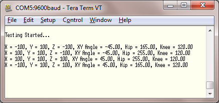
This program displays the joint angles for each corner of a 200mm square. The output from the terminal is...

Implementing the Program
As I learnt last time the implementation of the program is not quite as straight forward as just running the code and hooking up some servos. The angles need to be adjusted to suit the AX12+ servos. So 30° is subtracted from the hip and knee angles while 150° is added to (until I can think of better name for it!) the XY Plane angle.
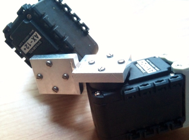
So the first thing I need to do connect the hip joint to the femur. This hip joint needs to operate with two degrees of freedom and ideally pivot around the same point in space. This is the first problem I run into. The brackets supplied with the AX12+ mean that there is no easy way to connect 2 servos together so that the pivot points are near each other - let along on the same point. I decide to do away with the supplied brackets and design my own. This new bracket connects two servos at right angles to one another in a manner that the centres of both servos are co-linear - i.e. they lie on a common imaginary line. The bracket with the two servos connected is shown below.

The distance between the two centres is exactly 30mm. This 30mm is important as is will directly effect to maths that controls the leg. To correct the maths so it moves the foot into the correct position I need to change a few things.
Firstly, while the calculation for the angle that the leg protrudes from the body (the XYAngle) doesn't change, the length of the leg (L) needs to be reduced to take into account the new bracket. The bracket will never contribute to the X axis (how far the foot moves forward) as the bracket is fixed on the YZ plane, but it will contribute to the Y and Z dimensions. The amount that each component is effected by the bracket depends on the length of the bracket (fixed at 30mm) and the XYAngle (calculated earlier). So the calculations become...
Y Component = 30 * cosine(XYAngle)
Z Component = 30 * sine(XYAngle)
These components must be subtracted from the Y and Z dimensions when L is derived. With this taken into account the code becomes...
// Then find out the length of the leg L
        float YComp = 30 * cos(XYAngle);
        float ZComp = 30 * sin(XYAngle);
        float L = (X*X) + ((Y-YComp)*(Y-YComp)) + ((Z-ZComp)*(Z-ZComp));
        L = sqrt(L);
Additionally I need to change the way that beta is calculated also to account for the bracket. Again I need to subtract the Y component contributed by the bracket from the Y value. So the code will become...
// Work out Beta
        float Beta = (float) X/((float) Y - YComp);
        Beta = atan(Beta);
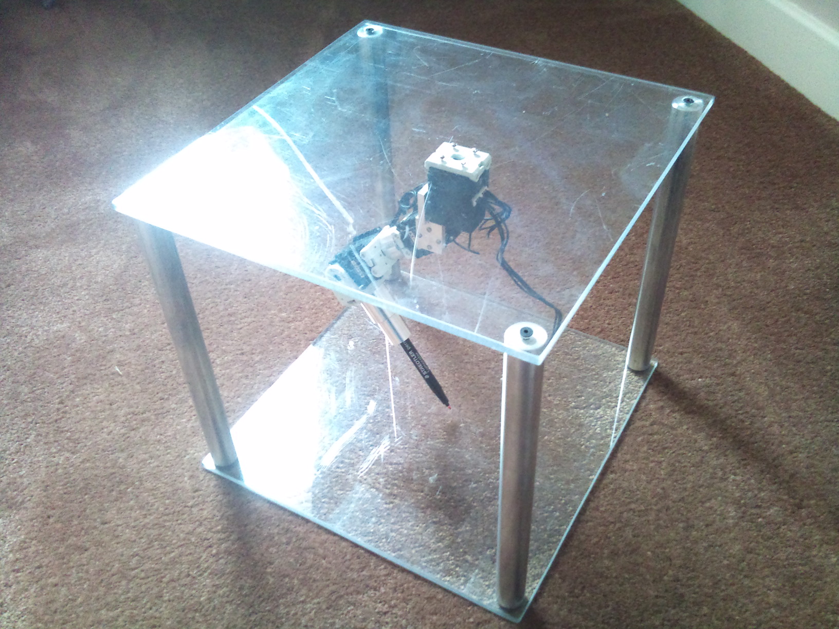
So that is probably enough from the software side of it, the next thing I decide to do is make up a frame to hold the leg steady while I test it. A few hours in the workshop later and I end up with...

1 comment on 3D Inverse Kinematics:
Please log in to post comments.

Great! I'll test it out now. thank you for sharing.