Using the ESP8266 to add Wi Fi to the mbed LPC1768
The ESP8266 is a WiFi SoC that can cost as little as $5 mounted on a PCB. Without shipping charges from Hong Kong, some are even available for under $3. It's has a RISC architecture
106micro Diamond Standard 80 MHz core (LX3) made by Tensilica with 64KBytes of instruction RAM,
96KBytes of data RAM, 64KBytes boot ROM, and an external 1M flash chip.
There are several pages elsewhere at mbed.org with info on the ESP8266 along with drivers and demo code. This page is for anyone using it with the mbed LPC1768 platform and the ESP8266 module currently available from Sparkfun. Code examples posted elsewhere with ESP8266 drivers have been modified for this mbed platform and the module Sparkfun is currently shipping (code elsewhere on other pages does not work with this module and the LPC1768 pins listed without a couple changes).
The ESP8266 comes with pre-installed firmware and the firmware seems to change a bit from older modules to newer modules. The default baud rate of 115200 can apparently change along with the exact command response with some of the different firmware versions. This also forces small changes in some of the codes communication timeouts. It is possible to load new firmware on the device and even write your own firmware, but the focus here is on using it with mbed with the default firmware to add WiFi support to this mbed. The default firmware uses a basic WiFi AT command set on a serial port with TTL levels. The mbed code examples send these AT commands and monitor or display the returned status messages. There is a new mbed library in development for the ESP8266, but these examples use the serial port directly to send the AT commands.
A Wi Fi access point or hotspot will be needed to use these demos. A PC or Mac can be used to setup a Wi Fi hotspot when there is not a Wi Fi access point already setup. Many Windows PCs with just Wi Fi can setup a PC mobile Wi Fi hotspot or hotspot using a Mac or new hotspot setup instructions for Windows 10. This chip can also be a Wi Fi access point, but that feature is not used in the demos here.
Wiring
It is not breadboard friendly in this module package, but with a half dozen M/F flexible jumper wires connected to the dual header pins it can quickly be hooked up to a breadboard. My module also needed a 330 uf decoupling capacitor across the 3.3V power lines - it seemed to reset often without this. Put the capacitor near the power pins for the module. It seems likely that at least some of the modules briefly draw just a bit too much power for this mbed platform - likely during a RF transmission burst at max power output. The data sheet says around 200mA, but some blogs report 250-300 mA Max. The capacitor will enable running these demos without a second power supply when nothing else is connected to mbed. To be 100% safe, whenever other devices are being used with mbed that take any significant current at all, another 3.3V supply should be used for the ESP8266 (with the grounds tied together). A second 0.1 uf capacitor from 3.3 to gnd might not be a bad idea for high frequency noise (it is not filtered by electrolytic capacitors as their C value actually drops off with increasing frequency). A small percentage of the modules still draw too much power even with the capacitor, and if they reboot often or reset mbed's power circuit (blue power LED blinks on and off slowly) they will require a second 3.3V supply. If a second supply is used for the ESP8266, connect the gnd to mbed's gnd!
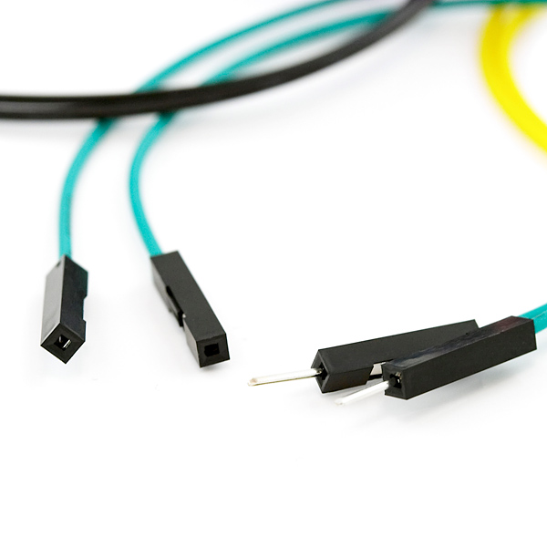
M/F flexible jumper wires for hookup of Sparkfun ESP8266 module
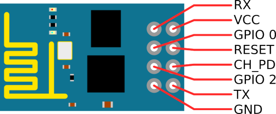
Pinout of Sparkfun ESP8266 module - top view with pins below
Warning
This is a 3.3V device - DO NOT connect to 5V (mbed VU(+5) pin is next to Vout(+3.3V) pin on LPC1768)!

Polarity and maximum voltage rating matters on electrolytic capacitors (most values over 1-10uf are electrolytic and have a "+" or "-" printed on the case along with the voltage rating, the longer lead is "+") - watch this video to see them blow up when this is not done correctly! This video from Sparkfun is actually more educational, but it does not has as many big explosions.
Wiring table for these demos
| ESP8266 | mbed LPC1768 | 330uf cap | |
|---|---|---|---|
| Vcc | Vout-3.3V | + | Note: The ESP8266 really needs an external 3.3V supply to work for all chips reliably |
| Gnd | Gnd | - | |
| Reset | p26 | ||
| RX | p28-TX | ||
| TX | p27-RX | ||
| CH_PD | Vout |
If an external DC power supply is used for the ESP8266 module, the capacitor can be omitted. Reset is kind of optional, but code was added to force a hardware reset at the start of some of the demos here. It can help, when it really locks up in a strange state and it can save the step of manually cycling the power. A red LED on the ESP8266 module will light up when it gets the correct power. A dimmer blue LED flashes when it is sending serial data. Other serial pins could be used, but will require editing the code demos. The module is a bit picky about connections and prone to reset, if the wires or module moves. It runs the demos OK, but after several minutes of operation, the module will still occasionally reset (perhaps a firmware and/or power supply issue?).
Other ESP8266 Boards
The module is also available on other PCBs that are a bit more breadboard friendly, but they are also a bit more expensive and some are currently out of stock. They may have a different version of the firmware and some older ones have a 512K and not the newer 1M flash chip and firmware. For critical applications, it might be worth the extra couple of dollars to get the new larger breadboard friendly modules with an on-board voltage regulator and/or use the alternative NodeMCU firmware. Some of the new ones now have FCC approval.
Adafruit ESP8266 Huzzah
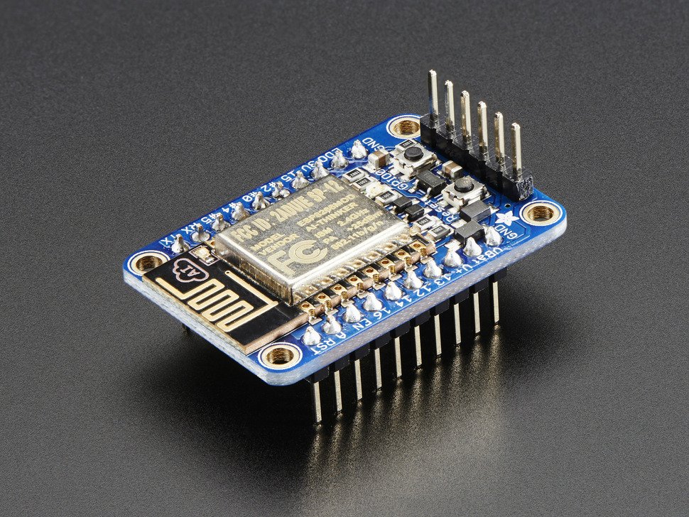
Newer ESP8266 Huzzah module from Adafruit. The FCC approved ESP8266 modules have a metal cover to reduce RF emissions.
Wiring for Adafruit ESP8266 Huzzah
The Huzzah draws too much current (5V 500MA max) to use mbed's USB based power supply and will need a second 5V DC power supply. It powers up at 9600 baud with the NodeMCU firmware running Lua. A Lua command tutorial is available. The two demo programs later on this page will not run on this firmware, but an mbed serial passthrough program can be used with a terminal application window to experiment with it by typing in commands. Just hook up power, two serial pins to mbed, and start a terminal application program running at 9600 baud connected to mbed's USB virtual com port (don't hookup reset pin to try this). There is an mbed ESP8266 class driver in development for the NodeMCU firmware and it uses the reset pin. The NodeMCU firmware supports DNS and use of the ESP8266 I/O pins. The Huzzah also has a reset and bootloader pushbutton on board.
| Huzzah | mbed LPC1768 | External 5V DC supply >=500MA |
|---|---|---|
| gnd | gnd | gnd |
| TX | RX - p27 | |
| RX | TX - p28 | |
| V+ | 5VDC | |
| RST | p26(optional) |
Sparkfun ESP8266 Thing
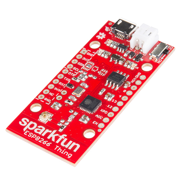
Sparkfun's ESP8266 Thing is another option, but it comes with no preinstalled firmware. It will need to be flashed with the AT command firmware prior to use. The USB connection is for power only. It can also run off of a 5V input or battery.
Code Demos
If you have the small ESP8266 module (and not the Huzzah or another module with the alternative Node MCU firmware), here are several basic WiFi demos to try on the LPC1768 mbed platform based on earlier examples from Paul Staron for a different mbed and different ESP8266 firmware. A terminal application program should be running at 115200 baud attached to your mbed's USB com port (the mbed com number varies). It will display the mbed WiFi commands and status messages sent out via mbed's USB virtual com port by the example programs. Teraterm sometimes gets in a mode where it displays bad characters at very high baud rates like 115200. RealTerm seems to be a more reliable option for these demos.
The first program will allow you to check if your setup is working and that you get a valid IP address from a WiFi router. After downloading the code to your compiler window, there is a line with your individual WiFi setup's "SSID" and "password" field that you will need to find and change, then recompile and download. This change is needed to connect to your WiFi and get an IP address. In this code, the SSID and password data is found in "main.cpp". Once you set it, the chip remembers it. Some WiFi security settings may require the MAC address of the device and this information is also displayed. So you need to run this first program first and get it working with a valid IP address for your ESP8266 before trying the second example. It displays status messages that will help, if there are problems with your initial Wi Fi setup.
Import programESP8266-configuration-mbed-LPC1768
Setup and test the ESP8266 Wi Fi SOC from Sparkfun. Sets SSID and PASSWORD and prints status messages. For use on mbed LPC1768. Also reports IP and MAC address. See https://developer.mbed.org/users/4180_1/notebook/using-the-esp8266-with-the-mbed-lpc1768/
Once your Wi Fi setup gets a valid IP, try this second example. The second example sets up some of the mbed pins as an IoT device controlled with a web page via any browser using the stored WiFi settings from the first program. You will need to note the IP address in the terminal application window for use in the web browser used to talk to your ESP8266/mbed web server. IP addresses must be used in the browser to connect since it does have DNS and you did not pay for a registered domain name.
Import programESP8266-WEB-Mbed-LPC1768-Controller
For ESP8266 Wi Fi SOC from Sparkfun on the mbed LPC1768. Sets up a web page server that can control a few mbed pins. Nice IoT demo. Need to configure Wi Fi SSID and PASSWORD first with another program first (one time only). See https://developer.mbed.org/users/4180_1/notebook/using-the-esp8266-with-the-mbed-lpc1768/ for more info.
In any web browser on just about any device on the same subnet, connect using the IP address once the program gets started and prints a "++Ready++" message to the terminal application program window. This takes several seconds, so watch for it in the terminal application window status messages. Change output pins by clicking on the box with a mouse and then hit the send- refresh button to update. For a quick demo, turn mbed built-in LED 1 on (click LED 1 on box and hit the send button) and then off (click LED 1 off box and hit the send button) while watching the mbed LEDs. Check the code to see the pins that it changes and reads for the web page. The web page HTML is all hard coded in C (not in a file). To read digital inputs, tie a digital output pin to a digital input pin with a jumper wire. You can change that output pin and watch the input pin change that is connected with the jumper wire. It also updates the time each time you reload the page using mbed's RTC. The analog inputs are floating (unless you add something), so you will probably notice a tiny change on the analog inputs each time the page is refreshed just due to the noise levels present on a floating analog input pin.
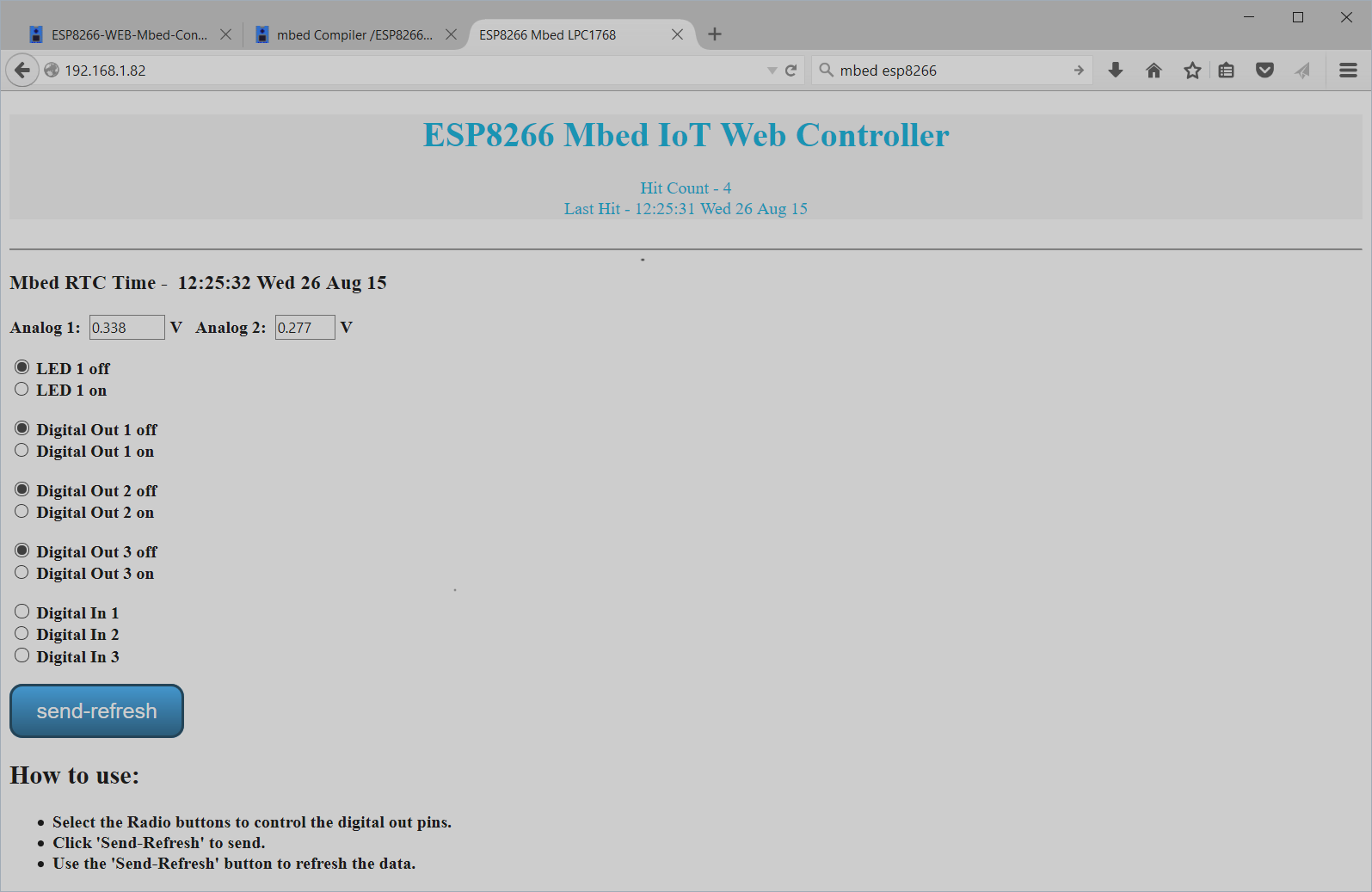
Sample Web page in browser from mbed server demo
The other demo programs for the 8266 use a new class just being developed for the ESP8266, but the 3 I/O pins (Rx, TX, reset) in the ESP8266 class constructor will need to be changed over for the mbed LPC1768 platform setup suggested here (i.e., p28,p27,p26) along with the Wi Fi "SSID" and "password". Some of the code also connects to demo servers using IP addresses that might need to be changed. It is still probably a good idea to get the first two programs here working first to confirm that basic Wi Fi is all working OK on your hardware setup before moving on to these more complex examples.
Huzzah Web page demo
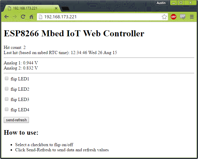
Web page from Adafruit Huzzah running NodeMCU Firmware
For those using the Adafruit Huzzah with the alternative pre-installed NodeMCU Lua-based firmware, a similar web page mbed IoT control demo is also available with additional instructions and a video.
ESP8266 Firmware Updates Using mbed
The firmware is being updated at a somewhat fast pace on the ESP8266. There is also alternative firmware that can be used. From some vendors, it may need a firmware update right out of the box. Special ESP8266 Firmware update info and instructions using mbed to program the flash are available (no FTDI module is needed for programming). It is still a bit confusing about which firmware to use (depends on features needed), which is the newest version, and exactly where to get the newest version. The recent ones from Sparkfun run this demo without a firmware update (AT 0.25 & SDK 1.1.1 version on it). This GitHub site seems to have even more recent versions of the firmware. NodeMCU, an alternative firmware with a few additional features such as DNS is also available.
Other ESP8266 Related Document Resources (not specific to mbed)
•NURDspace Wiki (Schematic, Datasheet, & More!)
•ESP8266 Community Forum
•GitHub (ESP8266 compiler)
•GitHub (GCC-Xtensa)
•Espressif ESP8266 site (company that makes the ESP8266)
•AI Thinker (company that makes the Sparkfun ESP8266 module - Translated using Google)
7 comments on Using the ESP8266 to add Wi Fi to the mbed LPC1768:
Please log in to post comments.

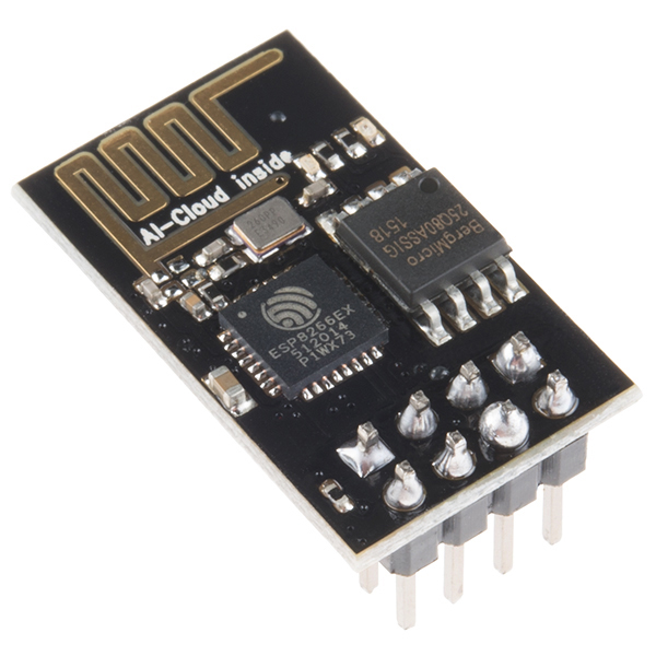

 I am facing the problem to get IP address. The component esp8266 shows red led indicator. I had just used coding provided by jim hamblen. I change the ssid and password. The wire connection between mbed lpc1768 and sparkfun esp8266 is ok. Is it connection of 330uF capacitor is a must? Anyone can give me some advise to troubleshoot it? Thank you
I have connected mbed lpc1768 with ESP01 and it works great, complete tutorial will be live soon. No library, simple UART interrupt and few functions to handle UART data. Using AT commands at 230400 baud rate.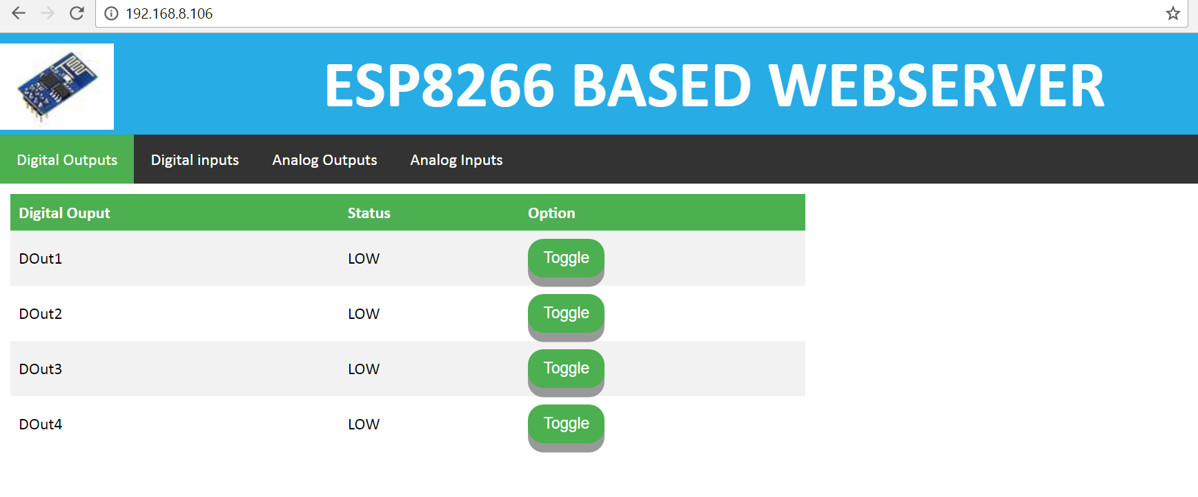
https://youtu.be/FOXCza6HQII