Using RGB LEDs
An RGB LED is actually three LEDs, red, green, and blue inside one package. LEDs need to be turned on and off very fast for dimming (changing the voltage across it does not work like it does in incandescent bulbs).The on and off times are so fast that human vision does not see a flicker on the LED and only the average value is perceived. Three PWM output bits would normally be used so that the brightness of each of the three LEDs can be controlled independently. In the mbed APIs, three PWMOuts would be used to control the RGB LED. A PWM value of 0.0 would be off and a 1.0 full on for each color LED. This allows a program to vary both the color and brightness level of the LED. Typically an RGB LED has four pins. One common pin and one for each of the three LEDs. In the LED seen below, the common pin is the longest pin. If hardware PWM pins are not available, SoftPWM can produce PWM signals on any pin by using software with timer interrupts.
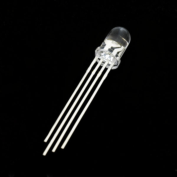
Sparkfun RGB LED
A voltage dropping resistor is needed to drop the output voltage of a digital logic signal to the operating voltage of the LED. Typically they run around 2.2 volts, but can be higher. By checking the current level in the LEDs data sheet, the value of the required dropping resistor can be calculated so that it drops down the voltage by the required amount from the digital logic output level (5 or 3.3V). Since the resistor is in series with the LED they both have the same current. Resistor values are typically around 100-330 ohms. The three LEDs inside a single RGB LED often have different operating voltages and current levels, so check the datasheet. A red LED typically needs about 2 volts. The voltage drop tends to rise as the frequency of the light wave increases. A blue LED may drop around 3 volts. The equations used to compute the correct resistance for an LED can be found in this Wikipedia series resistance formula or use this web page calculator. In some cases, the digital logic output driver circuit might have an internal voltage drop when providing around 2-20ma current for the typical small indicator LED and this could also reduce the value of the resistance used a bit. Brighter high-power LEDs require higher current levels and special driver circuits.
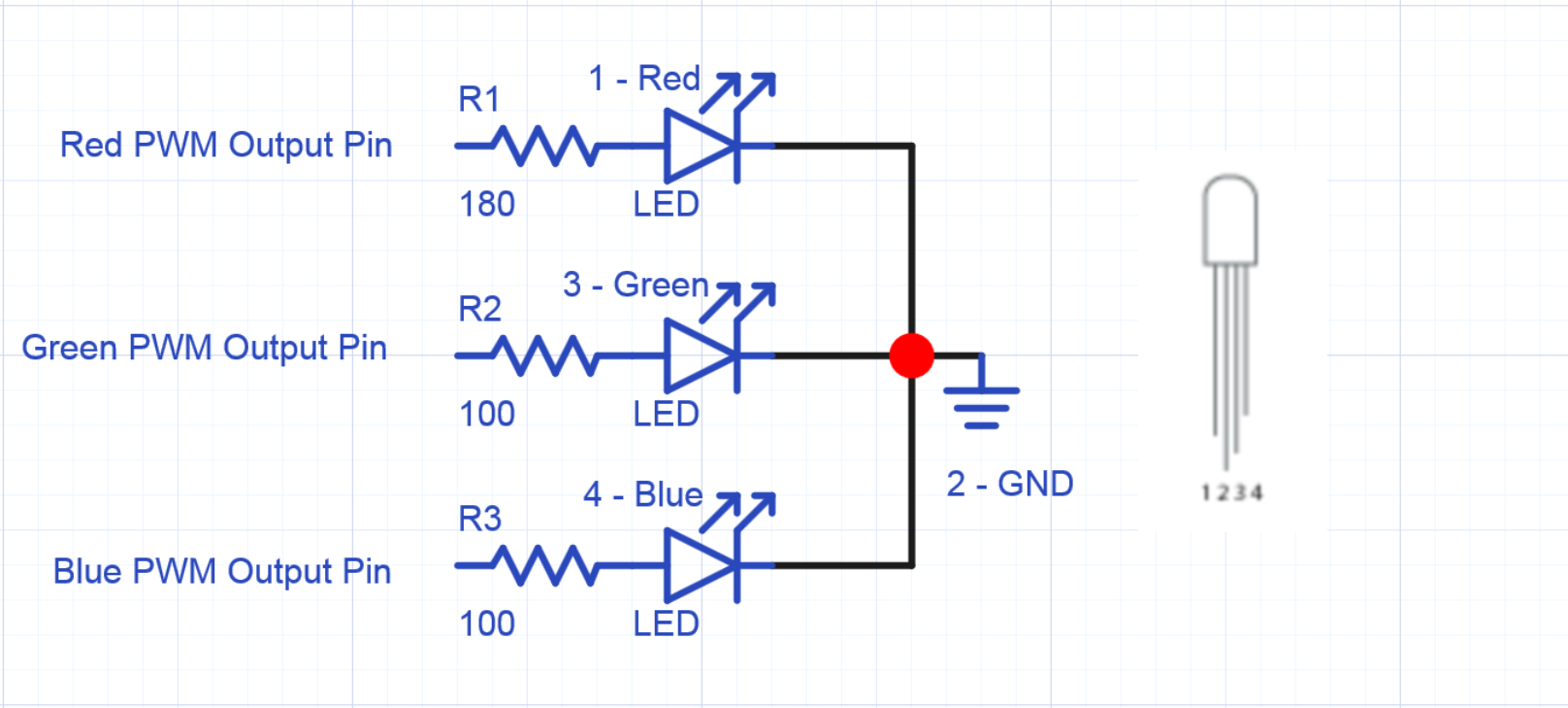
Wiring for Sparkfun's common cathode RGB LED. Resistor values shown above are for 5V logic (not 3.3!). For 3.3V on this RGB LED, the resistor values should be around 68, 10, and 10.
If the LED is wired to an output pin to turn it on and off in software (and not directly to power) there is already a small amount of resistance present in the microprocessor's output pin driver circuit that limits current from 5 to perhaps as much as 40MA, but most engineers still include the series resistor even for 3V blue LEDs in a 3.3V circuit to be safe. Any value close will work for the LED series resistor, it just might not be a bright as possible when using larger values.
Resistors are needed on LEDs!

Sparkfun's demo of an LED burning out in a quick flash without a dropping resistor when connected to a 5V power supply.
Larger resistors can be used such as 220 or 330 ohms to build a quick prototype, if the exact value is not available. This will reduce the brightness level of the LED, but will still be bright enough for most purposes.

A 180 ohm 1/4 watt resistor
Through hole resistors with long wire leads are typically used in breadboards to build prototypes. They are marked with resistor color code bands that specify the value in ohms.
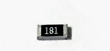
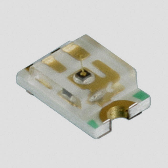
A surface mount Resistor and LED
An actual product these days would be more likely to use the smaller surface mount resistors and surface mount LEDs like those found on mbed modules. It results in smaller devices and mass production is easier and less expensive using modern surface mount automation equipment.
The four leads on the RGB LED are spaced a bit closer than the holes found in a breadboard. On most breadboards, the RGB LED fits a bit easier and requires less lead bending, if it is placed on the column of IC pins right next to a power bus and the long pin can go directly in a gnd power bus pin. The other three leads can go into three sequential IC contact points on the breadboard. Note: some RGB LEDs are common anode, in these the common pin is Vcc and PWM values of 0...1 are reversed to 1...0 in software.
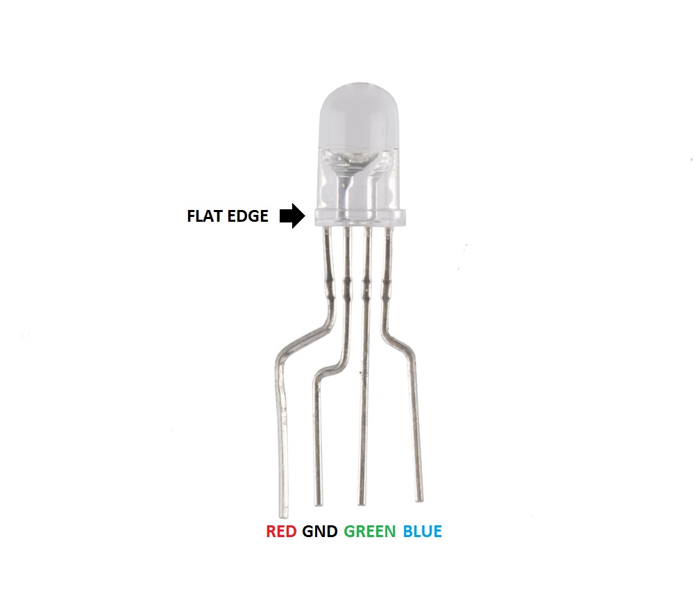
Sparkfun RGB LED pinouts
Here is a code example for mbed using a new class and three PWM output pins to control the RGB LED
#include "mbed.h"
//Class to control an RGB LED using three PWM pins
class RGBLed
{
public:
    RGBLed(PinName redpin, PinName greenpin, PinName bluepin);
    void write(float red,float green, float blue);
private:
    PwmOut _redpin;
    PwmOut _greenpin;
    PwmOut _bluepin;
};

RGBLed::RGBLed (PinName redpin, PinName greenpin, PinName bluepin)
    : _redpin(redpin), _greenpin(greenpin), _bluepin(bluepin)
{
    //50Hz PWM clock default a bit too low, go to 2000Hz (less flicker)
    _redpin.period(0.0005);
}

void RGBLed::write(float red,float green, float blue)
{
    _redpin = red;
    _greenpin = green;
    _bluepin = blue;
}
//class could be moved to include file


//Setup RGB led using PWM pins and class
RGBLed myRGBled(p23,p22,p21); //RGB PWM pins

int main()
{
    while(1) {
        myRGBled.write(1.0,0.0,0.0); //red
        wait(2.0);
        myRGBled.write(0.0,1.0,0.0); //green
        wait(2.0);
        myRGBled.write(0.0,0.0,1.0); //blue
        wait(2.0);
        myRGBled.write(1.0,0.2,0.0); //yellow = red + some green
        wait(2.0);
        //white with a slow fade to black dimming effect
        for (float x=1.0; x>=0.0001; x=x*0.99) {
            myRGBled.write(x, x, x);
            wait(0.005);
        }
        wait(2.0);
    }
}
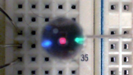
At the end of the demo code loop, all LEDs are dimmed very low and it is possible to see the three different LEDs inside.
As seen in demo code for yellow, often the three LEDs in an RGB LED have different light intensity level outputs and some color scaling by adjusting the PWM values may be warranted for improved color matching. From the datasheet, the green LED is around 5x brighter than red and blue. The data sheet's LED intensity levels could be used to add automatic scaling of PWM signals in the class code (i.e., something like "_greenpin = green *0.2;" in the class write member function code above). If you want to avoid typing the three float arguments for common colors each time they are needed, they can be setup once using #defines such as "#define red 1.0,0.0,0.0" and then just use "myRGB.write(red);".
For those that would like to use some more advanced C++ OO features, additional ease of use improvements can be made at the expense of a bit of memory and execution time as in the second code example below. It adds a new color class to hold the three color values, an RGBLed.write function using the new color class for its argument, and RGBLed operator = overloading for the color class. Then a simple statement such as "myRGBLed = red;" will work correctly. It now works just as easy as mbed's built in monocolor LEDs, but it adds color.
In addition, operator overloads for color "*" by a float change the brightness level without changing color, and the "+" operator can even add two colors (as long as they don't saturate and go above 1.0 on each color).
#include "mbed.h"

//class for 3 PWM color values for RGBLED
class LEDColor
{
public:
    LEDColor(float r, float g, float b);
    float red;
    float green;
    float blue;
};
LEDColor:: LEDColor(float r, float g, float b)
    : red(r), green(g), blue(b)
{
}
//Operator overload to adjust brightness with no color change
LEDColor operator * (const LEDColor& x, const float& b)
{
    return LEDColor(x.red*b,x.green*b,x.blue*b);
}
//Operator overload to add colors
LEDColor operator + (const LEDColor& x, const LEDColor& y)
{
    return LEDColor(x.red+y.red,x.green+y.green,x.blue+y.blue);
}

//Class to control an RGB LED using three PWM pins
class RGBLed
{
public:
    RGBLed(PinName redpin, PinName greenpin, PinName bluepin);
    void write(float red,float green, float blue);
    void write(LEDColor c);
    RGBLed operator = (LEDColor c) {
        write(c);
        return *this;
    };
private:
    PwmOut _redpin;
    PwmOut _greenpin;
    PwmOut _bluepin;
};

RGBLed::RGBLed (PinName redpin, PinName greenpin, PinName bluepin)
    : _redpin(redpin), _greenpin(greenpin), _bluepin(bluepin)
{
    //50Hz PWM clock default a bit too low, go to 2000Hz (less flicker)
    _redpin.period(0.0005);
}

void RGBLed::write(float red,float green, float blue)
{
    _redpin = red;
    _greenpin = green;
    _bluepin = blue;
}
void RGBLed::write(LEDColor c)
{
    _redpin = c.red;
    _greenpin = c.green;
    _bluepin = c.blue;
}

//classes could be moved to include file


//Setup RGB led using PWM pins and class
RGBLed myRGBled(p23,p22,p21); //RGB PWM pins

//setup some color objects in flash using const's
const LEDColor red(1.0,0.0,0.0);
const LEDColor green(0.0,0.2,0.0);
//brighter green LED is scaled down to same as red and
//blue LED outputs on Sparkfun RGBLED
const LEDColor blue(0.0,0.0,1.0);
const LEDColor yellow(1.0,0.2,0.0);
const LEDColor white(1.0,0.2,1.0);

int main()
{
    while(1) {
        myRGBled = red;
        //myRGBled.write(1.0,0.0,0,0); //red
        wait(2.0);
        myRGBled = green;
        //myRGBled.write(0.0,1.0,0.0); //green
        wait(2.0);
        myRGBled = blue;
        //myRGBled.write(0.0,0.0,1.0); //blue
        wait(2.0);
        myRGBled = red + green; //yellow = red + green
        wait(2.0);
        //white with a slow fade to black dimming effect
        for (float brightness=1.0; brightness>=0.0001; brightness*=0.99) {
            myRGBled = white * brightness;
            wait(0.005);
        }
        wait(2.0);
    }
}
The brightness or dimming control in the demo code, can come in handy for other LED lighting effects.
RGB LED modules with PWM driver ICs
LEDs are so widely used that many custom PWM LED driver chips are available. Many LED driver ICs provide a constant current level for the LED and do not need a resistor in series on each LED. There are also small breakout boards with both the PWM driver circuit IC and the RGB LED such as the Shiftbrite and Neopixel. These are handy when multiple RGB LEDs are needed and built in PWM hardware outputs are in short supply. There are also code examples in the mbed.org cookbook for the Shiftbrite and Neopixels. Most use a shift register or SPI style digital interface.

A ShiftBrite RGB LED module can display over one billion different colors. Its Allegro A6281 driver IC has 10 PWM control bits for each LED.
A 2D array of Shiftbrites connected in a long 1D SPI chain can be used to display images. Two sine functions in the row and col directions modulate the RGB LED colors used for this demo. A phase shift is used to move the wave.
![]()
Neopixel breakout boards hooked up in a single SPI (shift register) chain
![]()
A Neopixel strip
![]()
8 by 8 panel of Neopixels
![]()
Neopixel in a standard LED package. All Neopixels have a built in WS2811 PWM-based LED driver IC.
RGB Neopixels are available in several form factors. Like Shiftbrites they can be chained and are addressable. Sparkfun also has some of the Neopixel products in addition to Adafruit.
Demo code for several classic LED lighting effects using mbed is also available.
Industrial Applications
LEDs and RGB LEDs are widely used in status and power indicators in electronic devices. Home lighting is switching over to LED technology for more energy efficiency.
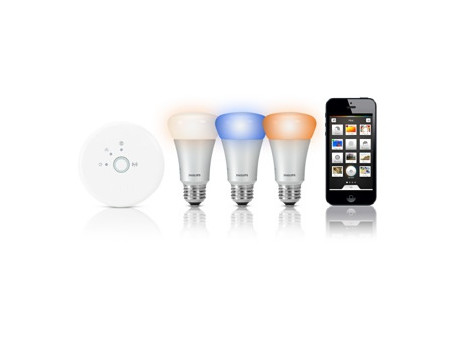
Philips Hue System controls RGB LEDs with a Wi Fi hub and Zigbee.
A few new home lighting systems use RGB LEDs to control both the brightness and the color of the lighting from a smartphone.
RGB LED Rings
Using a circular ring of RGB LEDs for status indicators is becoming very popular on new IoT devices such as the Nest smoke alarms (seen below), Amazon Echo, and Google Home. They change colors and use flashing and spinning/rotating lighting effects.

The new Nest Protect IoT smart smoke and CO alarm uses different LED colors to indicate status on a stylish light ring. It also turns white to provide an automatic nightlight. A Light level sensor and PIR motion detector triggers the light when someone walks nearby. The light ring uses five RGB LEDs. A circular sweeping light effect is also used.
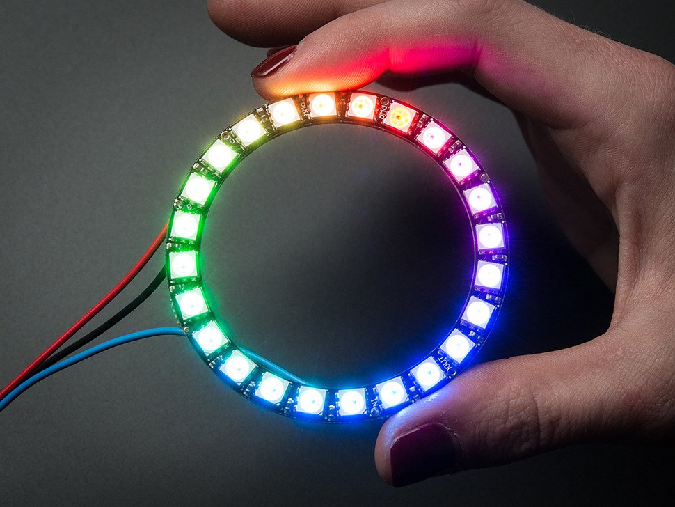
For easy prototypes of such devices, Adafruit has circular boards with RGB LEDs and drivers arranged in different size rings such as the one seen below.
Plumbing Fixtures

Even modern plumbing fixtures are now adding LEDs. The LED color indicates water temperature.
Digital Signs and Large Outdoor Displays
Another growing application area is digital signage and huge video displays. A large 2D array of pixels each built using a red, green, and blue LED or an RGB LED, is used to display images. Many digital signs include a network or WiFi connection that is used to download new images to display, so they could be considered to be an IoT device.
Daktronics, originally a startup company founded by two electrical engineering professors from South Dakota State University, uses millions of LEDs to make outdoor signs, scoreboards, and the huge video displays used in stadiums and lighted building exteriors around the world. Each pixel in the image has an red, green, and blue LED. The largest display in the world is being made by them for the new Atlanta Football Stadium. A recent local TV news story said it will contain 50 million LEDs. The largest display is currently in a Florida stadium and costs for that display ran just under $18,000,000.
A recent CBS Network News story on Daktronics
IR controlled RGB LED mouse ears at Disneyland with a TI microprocessor
Air Force Drone Light Show - 500 Drones with RGB LEDs
1 comment on Using RGB LEDs:
Please log in to post comments.


Nice presentation, thank you!