I2C access examples
Information
Japanese version available in lower half of this page.
このページの後半に日本語版が用意されています.
I2C access examples
I2C device register access examples (using PCA9532 and ISL29003)
Information
This page has been written as a supplement for LPCXpresso base board I2C device operation examples.
write
I2C class "write()" function sends I2C address and data on I2C bus.
The write function takes 3 arguments: slave_address, pointer to an array and length of the array.
With those parameters, the mbed SDK manages multiple bytes transfer automatically. The function will be returned when the transfer completed.
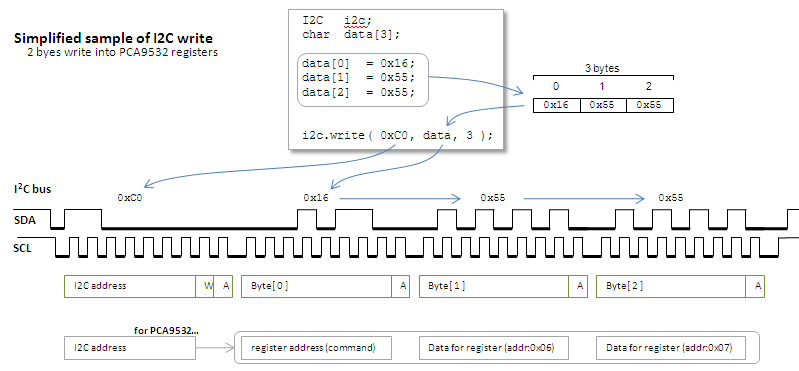
Following code and figure are showing 3 bytes data (0x16, 0x55 and 0x55) are written into a slave device which as address of 0xC0.
Warning!
The I2C 7 bit address should be given a MSB justified byte data.
For instance, if the slave device has address of '1100000' (7 bit binary), it should be given as '0xC0'. In this notation, the LSB doesn't need to be cared. The 8th bit after 7 bit slave address should be read or write bit and it is provided (overwritten) by mbed-SDK (inside of the write function).
If you are familiar to the LSB justified representation and want to use it in your program, it may be good idea to use it with 1 bit left shift operation like '(0x60 << 1)'.
#include "mbed.h"

I2C    i2c( p28, p26 );        // sda, scl

int main() {
    char    data[3];

    data[0]   = 0x16;
    data[1]   = 0x55;
    data[2]   = 0x55;

    i2c.write( 0xC0, data, 3 );
}

Information
The program is accessing 2 registers (8bit registers) in PCA9532 to control its 16 ports.
Basic register access of this chip requires two byte data after slave address. This two byte data should be register address and data for the register.
This operation is simple but having big over head. Because with this format, one register write needs whole I2C transfer each time.
To minimize this overhead, PCA9532 supports 'auto address increment' access.
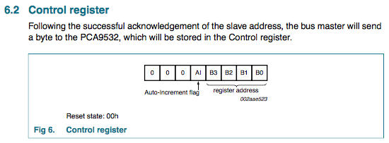
When specifying the register address, set a flag on bit 4. With this setting, the auto increment is enabled then consecutive following data are set into registers in contiguous addresses.
In the sample code, transferring data are prepared as array. First byte is for
the register address 0x06 and auto increment flag.
With this setting, following 2 bytes data will be written into registers of 0x6 and 0x7.
Information
The function returns zero when the transfer done successfully. It returns non-zero if the transfer got error such as NACK from slave or arbitration lost.
read
To read a register, it needs to be done by two I2C transfers.
1st transfer is "write" to specify the register address.
2nd is read from the register.
Next sample is a function that execute those two transfers and returns read 8 bit information.
short read_sensor_lower_8bit( void )
{
    char    v;
    char    cmd;

    cmd    = 0x05;

    i2c.write( 0x88, &cmd, 1 );
    i2c.read( 0x88, &v, 1 );

    return( v );
}

Information
Almost I2C compatible devices can read the register with this sequence but some may not.
Those devices needs to have "repeated-START condition" instead of "STOP and START".
Each write and read functions generates STOP conditions at the end of transfer. To disable this STOP condition generation, you can use optional 4th argument for the functions.
same_as_previous_sample
    i2c.write( 0x88, &cmd, 1 );  //  generates "STOP condition" at the end of write transfer.
    i2c.read( 0x88, &v, 1 );
how_to_connect_transfers_by_repeated-START_condition
    i2c.write( 0x88, &cmd, 1, true );  //  no "STOP condition" generated
    i2c.read( 0x88, &v, 1 );           //  "START condition" for this transfer becomes a "repeated-START" condition
reference:
LPCXpresso base board I2C device operation examples
http://mbed.org/users/okano/notebook/lpcxpresso-base-board-i2c-device-operation-example/
mbed library - I2C
http://mbed.org/handbook/I2C
PCA9532
http://www.nxp.com/documents/data_sheet/PCA9532.pdf
ISL29003
http://www.intersil.com/data/fn/FN7464.pdf
LPCXpresso base board
http://www.embeddedartists.com/products/lpcxpresso/xpr_base.php
I2C-bus specification and user manual
http://www.nxp.com/documents/user_manual/UM10204.pdf
update info
- 03-May-2010 : 1st version (in HTML)
- 12-Sep-2014 : converted to Wiki format and some words are added
- 14-Sep-2014 : some modifications done. Japanese version added
I2Cアクセス例
I2C デバイスのレジスタ・アクセスの例 (PCA9532 と ISL29003での例)
Information
このノートページはLPCXpresso base boardの操作例の補足として書かれました
書き込み (write)
I2Cクラスの"write()"はI2CにI2Cアドレスとデータを送出する関数です.
このwrite関数は3つの引数をとります:スレーブ・アドレス,配列へのポインタ,そして配列の長さです.
これらのパラメータ(引数)を与えることにより,mbedSDKは複数バイトの転送を自動的に実行します.関数は転送の完了後に戻ってきます.
次の例は,3バイトのデータ(0x16, 0x55 and 0x55)を,アドレスが0xC0のスレーブ・デバイスに書き込むものです
Warning!
I2Cの7ビット・アドレスは「前詰め(MSB justified)」で指定します.
たとえばもしアドレスが'1100000' (7ビットの2進値)ならば,それを'0xC0'とします.この時の最後のビット(LSB)は気にしないで構いません.スレーブ・アドレスの7bitの次,8番目のビットは書き込みまたは読み出し指定のビットであり,mbed-SDKの関数(この場合はwrite関数)がこのビットを上書きします.
もし後詰め(LSB justified)の表現に慣れており,それを1ビットシフトした表記に直すのが面倒ならば,「'(0x60 << 1)'」と書くのもひとつの方法です.
#include "mbed.h"

I2C    i2c( p28, p26 );        // sda, scl

int main() {
    char    data[3];

    data[0]   = 0x16;
    data[1]   = 0x55;
    data[2]   = 0x55;

    i2c.write( 0xC0, data, 3 );
}

Information
プログラムはPCA9532の16個のポートを制御するために2つのレジスタ(8ビット・レジスタ)にアクセスしています.
このチップの基本的なレジスタ・アクセスは,スレーブ・アドレスと2バイトのデータ転送で行われます.2バイトのデータはレジスタ・アドレスとそこに書き込むデータです.
この転送は単純ですが非効率的です.なぜならこのやり方では,ひとつのレジスタ書き込みごとにI2Cの転送全部を行わなければならないからです.
これを効率的に行うためにPCA9532には「オート・アドレス・インクリメント」が用意されています.
レジスタ・アドレスの指定の際に4ビット目のフラグを立てておきます.この設定でオート・インクリメントが有効となり,以降のデータを連続したレジスタに書き込んで行くことができます.
コード例では転送するデータを配列として用意しています.
1バイト目はレジスタ・アドレスに0x06を指定し,さらに「オート・アドレス・インクリメント」のフラグが立てられています(0x16 == 0x06 | 0x10).
この設定により続く2バイトのデータはそれぞれ0x6と0x7のレジスタに書き込まれます.
Information
この関数は戻り値を持ちます.転送が成功すれば0が返ります.もしNACKやアービトレーション・ロストなどの問題が発生すると0でない値が返ります.
読み出し(read)
レジスタを読むには2つの転送を使います.
最初の転送は書き込み(write)転送で,読み出す対象のレジスタ・アドレスを指定ます.
2番目がレジスタの読み出しです.
次の例は,この2つの転送を行い,読みだした8ビットのデータを返す関数です.
short read_sensor_lower_8bit( void )
{
    char    v;
    char    cmd;

    cmd    = 0x05;

    i2c.write( 0x88, &cmd, 1 );
    i2c.read( 0x88, &v, 1 );

    return( v );
}

Information
I2C互換のほとんどのデバイスでこのような読み出し方法が使えますが,例外も存在します.
そのようなデバイスでは各転送の間に「STOPコンディションとSTARTコンディション」の代わりに「リピーテッドSTARTコンディション」が必要だったりします.
writeとreadの関数は,転送の最後にSTOPコンディションを発生させます.このSTOPコンディションを発生させないようにするために,4番目のオプション引数を与えることができるようになっています.
same_as_previous_sample
    i2c.write( 0x88, &cmd, 1 );  //  書き込み転送の最後にSTOPコンディションを発生させる
    i2c.read( 0x88, &v, 1 );
how_to_connect_transfers_by_repeated-START_condition
    i2c.write( 0x88, &cmd, 1, true );  //  STOPコンディションが発生しない
    i2c.read( 0x88, &v, 1 );           //  この転送のSTARTコンディションは「リピーテッドSTARTコンディション」となる
参考
LPCXpresso base board I2C device operation examples
http://mbed.org/users/okano/notebook/lpcxpresso-base-board-i2c-device-operation-example/
mbed library - I2C
http://mbed.org/handbook/I2C
PCA9532
http://www.nxp.com/documents/data_sheet/PCA9532.pdf
ISL29003
http://www.intersil.com/data/fn/FN7464.pdf
LPCXpresso base board
http://www.embeddedartists.com/products/lpcxpresso/xpr_base.php
I2C-bus specification and user manual
http://www.nxp.com/documents/user_manual/UM10204.pdf
更新情報
- 03-May-2010 : 1st version (in HTML)
- 12-Sep-2014 : converted to Wiki format and some words are added
- 14-Sep-2014 : some modifications done. Japanese version added
3 comments on I2C access examples:
Please log in to post comments.


Nice!
I had been stumped getting I2C to work, but this example got me straightened out.
Thanks!