Arch Pro is released
Page last updated
12 Dec 2013, by
 Seeed Studio
.
4
replies
Grove,
LPC1768,
shield
Arch Pro, an mbed enabled development board for rapid prototyping.

Overview
Arch Pro is a variant of mbed LPC1768 with build-in Ethernet, USB Host/Device, Grove connectors and Arduino form factor. With a variety of Shield/Grove hardware modules and lots of software libraries for Arch Pro, you can implement Ethernet, USB Host/Device and NFC applications rapidly and easily.

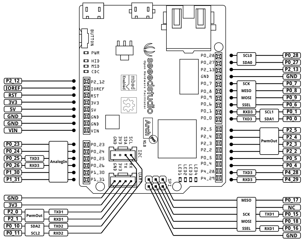
There is a monochrome version pinout of Arch Pro for you to print. A fritzing part of Arch Pro is also provided. Have fun!
Features
- mbed enabled
- Online development tools
- Easy to use C/C++ SDK
- Handy libraries
- Arduino form factor with two Grove connectors
- Drag-n-drop programming
- Debug using CMSIS DAP
- USB virtual serial for communication
- NXP LPC1768 MCU
- Powerful ARM Cortex-M3 core
- Up to 100MHz
- 512KB Flash, 64KB RAM
- Ethernet, USB Host/Device, 4xUART, 3xI2C, 2xSPI.
Applications
Order
Get one from Seeed Studio.
4 comments on Arch Pro is released:
Just noticed that the Arch Pro silkscreen for the Grove connectors is labelled 5V on the underside of the PCB, and 3V3 on top.
With R50 populated by default, they are almost always going to be 3V3.
Also noticed that on the pinout diagram above, the third pin from the top on the right hand side is mis-labelled (should be P2_13).
It would be very helpful it the pinout diagram had the corresponding standard mbed DIP pinouts for cross reference.
As far as I can tell from comparing schematics, the following are the mappings of the blue pins... hopefully helpful to someone.
Left hand side:
P2_12=N/A, P0_23=DIP15, P0_24=DIP16, P0_25=DIP17, P0_26=DIP18, P1_30=DIP19, P1_31=DIP20
Grove:
P2_0=DIP26, P2_1=DIP25, P0_10=DIP28, P0_11=DIP27
Right hand side:
P0_28=N/A, P0_27=N/A, P2_13=N/A, P0_7=DIP7, P0_8=DIP6, P0_9=DIP5, P0_6=DIP8, P0_1=DIP10, P0_0=DIP9,
P2_5=DIP21, P2_4=DIP22, P2_3=DIP23, P2_2=DIP24, P0_5=DIP29, P0_4=DIP30, P4_28=N/A, P4_29=N/A
SPI:
P0_17=DIP12, P0_15=DIP13, P0_18=DIP11, P0_16=DIP14
Grove VCC defaults to 3V3, but can be changed to 5V by moving R50 to R51
SPI VCC pin can be set by populating R52 (3V3) or R53 (5V) wirh 0R - neither populated by default
Hi Kean,
Thanks a lot.
P2_13 is fixed now. We will draw a pinout diagram with mbed LPC1768's pin name and add the document of Grove VCC and SPI VCC to wiki.
I'm a novice.
This board shows only 25kB of Flash,so I can't load any program.
However, Nucleo 401RE shows 512kB.
Does someone have information about that?
Hideo
Please log in to post comments.
Just noticed that the Arch Pro silkscreen for the Grove connectors is labelled 5V on the underside of the PCB, and 3V3 on top. With R50 populated by default, they are almost always going to be 3V3.