Automotive Stepper Motor

This project improves the original stepper motor driver shown in this link below. There are two improvements: add a calibration routine and a more robust driving method.
Original stepper motor page: https://developer.mbed.org/users/nhimani3/notebook/automotive-gauge-stepper-motor/
Description
Driving method
These stepper motors have 629 steps in total for single stepping for a full range of 315°. Equivalently each step is 0.5 degree. However, during the testing of the original stepper motor driver library, it is found that slipping often occurs, and the motor will often not go to the desired location. This is more noticeable if the motor is to rotate a small amount of steps, and thus the slipped steps will be relatively large compared to the total steps. Anyhow, this makes it difficult to integrate the stepper motor into any project that requires precision, which is the reason to use stepper motor instead of a DC motor anyway.
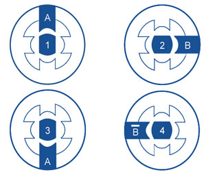
To solve this problem, the driving method in this improved driver library is changed from the original "wave drive" to the "2-phase drive" method. Simply put, 1 phase drive will excite one coil at a time. That coil will pull the motor by one step. Then the next coil will be excited and pull the motor by one step. An illustration is shown below. This method is prone to slipping due to its low starting torque (only one coil is acting on the motor).
Wave Drive (1 phase drive)

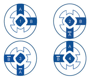
Alternatively, 2-phase drive excites two coils at a time. This aligns the motor to the middle of the two coils for each step, as shown below. This method will cost twice amount of power to drive the motor. However, since we are using an external 5V power supply for the H-bridge driver, the power consumption can be sacrificed for a better accuracy.
Two Phase Drive

For future reference, the driving method can also be changed to half-step or even micro-stepping. Our intention for this project is to reuse the original library files as much as possible. Changing to other driving methods will require some changes through the code and may affect other usages. Micro stepping method is briefly explored. It seems Mbed does not easily support two PWM outputs that have different rising edge. There is a way around that but it is not worth the efforts now that 2-phase drive gives a pretty good accuracy and performance.
Calibration routine
A stepper motor by nature is a open-loop control system. We can't know where is its location without adding in sophisticated (sometimes impossible) sensors. Therefore, it is crucial to have the motor start at a known position before it starts operation. Although users can manually rotate the motor using original library files, it is not good practice of programming as initial calibration is so often used. In this improved driver, I put the calibration routine inside the driver library.
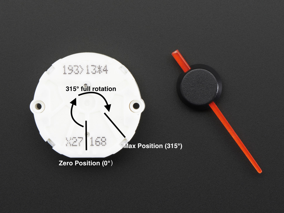
The concept of calibration is simple. The motor will be rotated in CW direction for full range (629 steps or 315 degrees) and rotated in CCW direction for full range. If it is starting in a non-zero position, it will be stopped at the 315 degree position. And a full rotation will bring it back to 0 degree position. This way, the motor is guaranteed to be in the zero position. An illustration is shown below.

One concern may be the speed of rotation. As we would expect, if the motor starts in non-zero position, it will "hit" the 315 degree location and be physically stopped by the mechanical block. Ideally we would like the speed to be as slow as possible to reduce the impact force. However, a too slow speed is unnecessary as it increases the start-up time of the system. The default speed we set is 400 (steps per second). It is not terribly slow but nor so fast that you can hear plastics bumping either. Users can change that to their application need. Overall we think the mechanical impact is very small and will not affect the lifetime of the motor.
Wiring Diagram
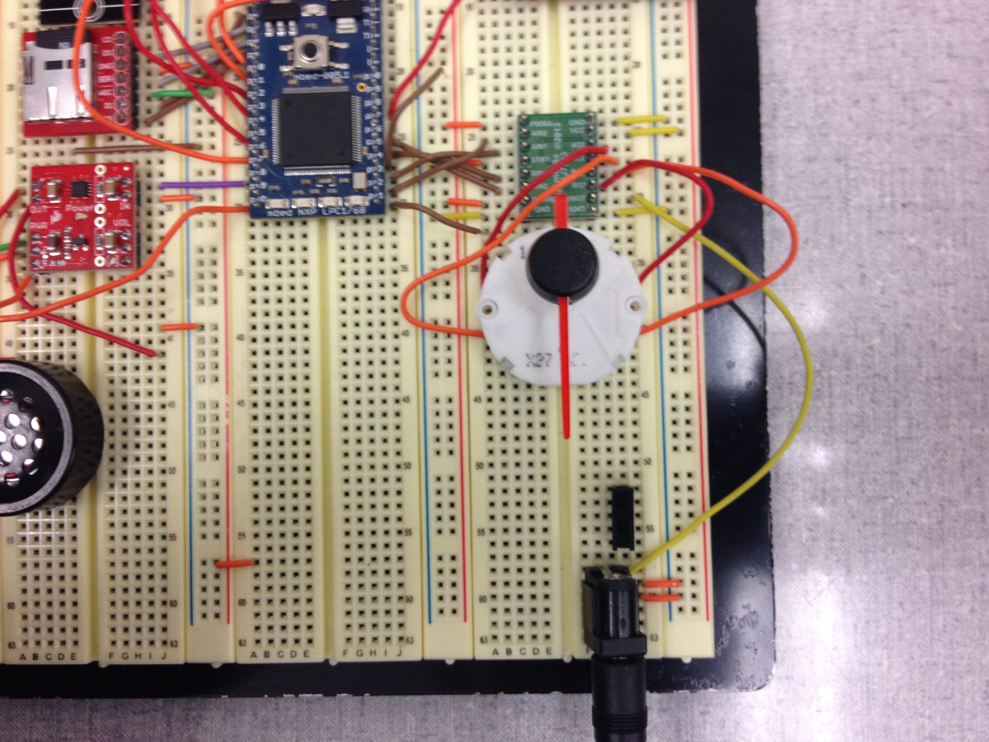
The wiring is the same as in the original wiki page, except the power and ground connections were missing. Here I have every connections listed.
| mbed | H-bridge | Stepper |
|---|---|---|
| gnd | gnd | |
| Vout | Vcc/PWMA/PWMB/STBY | |
| VU(5V)* | Vmot | |
| p26 | BIN2 | |
| p25 | BIN1 | |
| p23 | AIN1 | |
| p22 | AIN2 | |
| BO1 | Pole B1 | |
| BO2 | Pole B2 | |
| AO2 | Pole A1 | |
| AO1 | Pole A2 |

Video Demo
Calibration demo
In this video, I manually messed up the initial position of the motor. The init function calibrated the motor by rotating full range and return to the zero position. After that, the motor accurately went to all desired angles. The demo code is shown below.
Drive method comparison
The two videos compare the result of different driving methods. To see the difference, we set the speed to 800 steps per second, which is really fast for this stepper motor. As seen in the video, the original 1-phase driver will fail after the calibration routine (calibration routine is slower). The coil excitation is too peak to pull the motor around quickly. Therefore, the motor mostly remains stagnant. In comparison, the 2-phase drive method provides much more torque and the motor is pulled to different angled position without slipping.
Wave drive (1-phase drive)
2-phase drive
Note that as the speed decreases, the motor will tend to slip less. But the original method still has occasional problems where motor will go to a close but not exact angle. This behavior will be unpredictable. The new driver will not have this problem.
Demo Code for 2-phase drive with calibration
Here is the demo code for the 2-phase drive with calibration routine. The "init" function initializes the drivers and rotate the stepper motor to the maximum clockwise i.e 315° and returns the motor back to zero degree in counter clockwise directions and the angle_pos function moves the stepper motor to the desired input angle. The speed is set to 800 steps per second.
Import programStepper_Motor_Demo_final
Final version of stepper motor demo
Driver Library
Import library
Public Types |
|
| enum | Polarity |
|
Constants for motor rotate control. More... |
|
Public Member Functions |
|
| StepperMotor_X27168 (PinName A_f, PinName A_r, PinName B_f, PinName B_r) | |
|
Create a stepper motor object connected to specified DigitalOut pins.
|
|
| StepperMotor_X27168 (PinName A_f, PinName A_r, PinName B_f, PinName B_r, int init_step_position) | |
|
Create a stepper motor object connected to specified DigitalOut pins starting at specified position.
|
|
| void | set_speed (float s) |
|
Set the motor speed (i.e.
|
|
| int | get_speed () |
|
Get the motor speed (i.e.
|
|
| void | set_max_position (int p) |
|
Set the maximum steps the motor should take (not degrees)
|
|
| int | get_max_position () |
|
Get the motor maximum position (int steps not degress)
|
|
| int | step (int dir) |
|
Turn the motor one step (1/2 Degree)
|
|
| void | step_position (int pos) |
|
Turn the motor to a specific step.
|
|
| void | angle_position (float angle) |
|
Turn the motor to a specific degree angle with a resolution of 0.5 degrees.
|
|
| void | init () |
|
Initialize the motor by rotating CW for full range and CCW for full range.
|
|
Please log in to post comments.
