PCF8591 I2C 4 Channel, 8 Bit A/D and 1 Channel 8 bit D/A
The NXP (Philips) PCF8591 is an I2C 4 Channel, 8bit Analog to Digital converter which also includes a 1 Channel, 8bit Digital to Analog converter in the same package. Upto 8 devices can be connected to the same bus since it supports 8 different I2C slaveaddresses. Each analog input channel can be individually read from, but does not allow write. The analog output channel is write only and can not be read back. The device is a rather old design (early 1980s). However, it is still available and was used on the mbed LPC812 MAX board.
Hardware Schematic
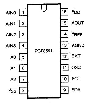
The PCF8591 is available in SMD and 16pin DIL.

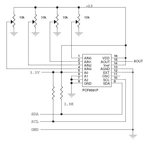
Typical circuitry is shown is shown in the NXP datasheet:

Note the device allows a wide range of supplyvoltages (2V5 .. 6V). The LPC812 and LPC1768 can use the native 3V3 I2C bus to control the PCF8591.
The PCF8591 supports single ended ADC inputs and differential ADC inputs. However, the differential mode is not available in this library to avoid problems when the mode could be reconfigured on-the-fly by different threads in user software.
Software Library
Control of the device is straightforward. There is one internal (write only) register to control the device mode (single or differential ADCs, selected ADC channel, auto-increment and DAC enable). The second 8bit write-only register is for the Digital to Analog converter. The valid range for the DAC register is 0 through 255. This results in 0V..Vcc.
The ADC channels may be read by simply reading from the PCF8591. The selected ADC channel should be set before reading the ADC registers. Note that the first byte is a dummy value and should be ignored!!!! Subsequent read operations can read all 4 ADC channels sequentially when the Auto-Increment mode is activated. The library does not use that feature and therefore each channel must be read separately.
The PCF8591 Class instantiation requires a pointer to an I2C object and a device slaveaddress. Methods are provided for setting DAC value and reading an ADC channel. Valid ADC and DAC ranges are 0..255.
Additional Classes are provided to emulate the behaviour of mbed AnalogIn and AnalogOut pins. These Class instantiations requires a pointer to an I2C object, a device slaveaddress and the ''Pinname''. Methods are provided for setting DAC value and reading the ADC channel. However, in this case the values are normalised to a range between 0.0f and 1.0f. The ''='' operator may be used on the AnalogIn and AnalogOut emulated pins.
The API documentation for the basic library
Import library
Public Member Functions |
|
| PCF8591 (I2C *i2c, uint8_t deviceAddress=PCF8591_SA0) | |
|
Create a
PCF8591
AD and DA object using a specified I2C bus and slaveaddress.
|
|
| void | setADCMode (uint8_t mode) |
|
Set ADC mode.
|
|
| void | setDACMode (bool mode) |
|
Set DAC mode.
|
|
| void | write (uint8_t analogOut) |
|
Write Analog Output.
|
|
| uint8_t | read (uint8_t channel) |
|
Read Analog Channel.
|
|
Protected Member Functions |
|
| void | _init () |
|
Initialise AD and DA driver.
|
|
The API documentation for the AnalogIn emulator library
Import library
Public Member Functions |
|
| PCF8591_AnalogIn (I2C *i2c, uint8_t channel, uint8_t deviceAddress=PCF8591_SA0) | |
|
Create a
PCF8591
AnalogIn object using a specified I2C bus and slaveaddress.
|
|
| float | read () |
|
Read Analog input.
|
|
| operator float () | |
|
An operator shorthand for
read()
|
|
Protected Member Functions |
|
| void | _init () |
|
Initialise DAC driver.
|
|
The API documentation for the AnalogOut emulator library
Import library
Public Member Functions |
|
| PCF8591_AnalogOut (I2C *i2c, uint8_t deviceAddress=PCF8591_SA0) | |
|
Create a
PCF8591
Analogout object using a specified I2C bus and slaveaddress.
|
|
| void | write (float value) |
|
Write Analog Output.
|
|
| PCF8591_AnalogOut & | operator= (float value) |
|
An operator shorthand for
write()
|
|
Protected Member Functions |
|
| void | _init () |
|
Initialise DAC driver.
|
|
The code is here
Import libraryPCF8591
Library for NXP (Philips) PCF8591 I2C 4 Channel, 8bit Analog to Digital converter and a 1 Channel, 8bit Digital to Analog converter.
Example
#include "mbed.h"
#include "PCF8591.h"

#define lpc812  1
#define lpc1768 0

//DigitalOut myled1(LED1);
DigitalOut heartbeatLED(LED1);

//Pin Defines for I2C Bus

#if (lpc1768)
// SDA, SCL for LPC1768
#define D_SDA                  p28
#define D_SCL                  p27
#endif

#if (lpc812)
// SDA, SCL for LPC812
#define D_SDA                  P0_10
#define D_SCL                  P0_11
#endif

//I2C Bus
I2C i2c_bus(D_SDA, D_SCL);

//PCF8591 adc_dac(&i2c_bus, PCF8591_SA0);
PCF8591 adc_dac(&i2c_bus);

PCF8591_AnalogOut anaOut(&i2c_bus);

PCF8591_AnalogIn anaIn(&i2c_bus, PCF8591_ADC1);


//Host PC Baudrate (Virtual Com Port on USB)
#define D_BAUDRATE            9600
//#define D_BAUDRATE            57600

// Host PC Communication channels
#if (lpc1768)
Serial pc(USBTX, USBRX); // tx, rx for mbed LPC800 MAX
#endif

#if (lpc812)
Serial pc(P0_4, P0_0); // tx, rx for LPC812 LPCXpresso
#endif

int main() {
  uint8_t analog;
  float ana;

  pc.printf("\r\nHello World from LPC812\r\n");

  while(1) {

    //pc.putc('*');

    wait_ms(20);

//    analog = adc_dac.read(PCF8591_ADC0);  // read A/D value for Channel 0 (LDR)
//    analog = adc_dac.read(PCF8591_ADC1);  // read A/D value for Channel 1 (potmeter)
//    pc.printf("%d ", analog);

    ana=anaIn;                                                    // read A/D value for Channel 1 (potmeter)
    pc.printf("%2.2f ", ana);

    anaOut = ana;                                               // write back A/D value to D/A Channel
  }


  pc.printf("Bye World!\n\r");
}
The Testsoftware for the PCF8591 (and the SAA1064) maybe found here: http://mbed.org/users/wim/code/812_hello/
I2C Blockwrite Troubleshooting!
Some issues were found with the LPC812 I2C blockwrite methods used in the first versions of this library. The problem is discussed here and was resolved by using the I2C byte read and write methods instead.
Have fun!
Please log in to post comments.
