Library for Princeton PT6301 VFD controller. Used in Futaba CIG VFD tubes.
This is a library for the Princeton PT6301 VFD controller. The controller is used by Futaba 'Chip In Glass' (CIG) VFD tubes. The device supports upto 20 Grids of 5x7 matrix segments for 2 rows of characters (A and B). It also supports 1 additional segment for 2 rows (A and B). In addition to the internal ROM character set, the PT6301 also supports 16 User Defined Characters.
The PT6301 has an SPI Serial interface. Control data consists of an 8-bit command and one or more data bytes. Command and data are sent LSB first and latched on rising edge of CLK. Idle CLK is high. Data address is auto incremented. Same for Icon and UDC addresses. The commands and data are transmitted during CE low and latched on rising CE edge.
The PT6301 has internal memory for all characters and icons. The content is automatically displayed on the tube. The memory consists of two banks (row A and row B) for character memory and two banks (row A and row B) for icon memory. Each of those banks is accessed by separate commands. However, these command do not support addressing individual locations in the memory. Memory updates always start at address 0 in the selected row A or B. Consequently, the whole displaymemory needs to be rewritten when any location (except for 0) is to be updated. The library therefor uses a local mirror memory to store the display content, update one or more characters in the mirror-memory as needed, and rewrite the whole display memory from the mirror-content. The write-back is performed by calling the 'refresh' method. Additional advantage of the mirror-memory is that we can also implement wrap-around and scrolling from row A to B for multi-line displays.
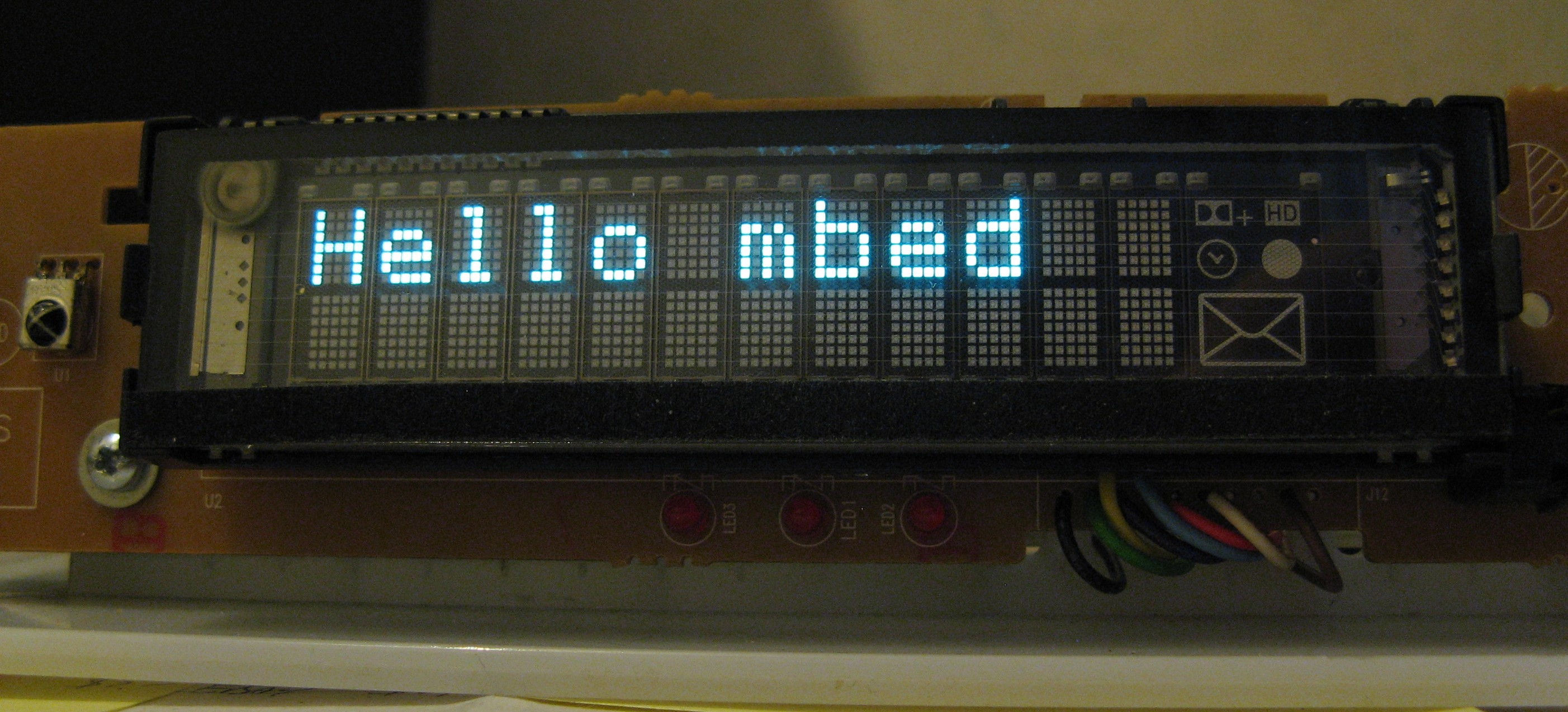
The lib was tested on displays salvaged from two Samsung cable TV receivers (e.g. Samsung SMT-C7140 and Samsung SMT-G7400). The examples don't use all features as this depends on how the controller has been applied inside the tube. The SMT-C7140 for example does not use the icon segments, but uses a separate grid to display a User Defined Character. The segments in the UDC light up specific icons (eg mail, clock). See picture below.

The example code is
Import programmbed_PT6301
Test for PT6301 VFD. First release.
I stumbled on the SMT-C7140 display and found some useful reverse engineering info by Codebeat here that helped to identify the controller. The pinout for the VFD tube connector (starting from the left side in the picture above) is: GND1, GND2, +35V DC (switched), 5V DC supply (switched), OSC pin (RC network between 5V and GND), /RST, /CS, CLK, DAT, NC, NC
The 35V DC is generated on the PCB by a DC/DC converter. The 35V generator, the 5V supply and the filament supply are all enabled by a pin on the connector at the bottom of the PCB.
The SMT-G7400 had a similar schematic for the tube connection as the SMT-C7140, but used a dedicated processor on the display PCB. The processor was removed and replaced by flying wires to an mbed LPC1768 for testing with the lib.
General explanation of VFD is here
