Self-Adjusted Robo-Boat with PID Control Loop
Import programRC_boat
RC Boat using a C# GUI over XBee communication.
Team RoboBoat, Georgia Tech (Ria Gupte, Tianhao Li, Andrew McRae, Mitchell Pang)
Introduction
This wiki page illustrates the process of adapting a simple "Full-on Full-off" RC boat (found the boat on Amazon) into a more complex robo-boat with accurate PID control loop and precise velocity monitoring using mbed, H-bridge, IMU (inertial measurement unit), and XBee transceiver. The fully modified boat can be controlled by a remote Windows GUI running either on a laptop or on a mobile device through XBee's 802.15.4 radio link (2.45 GHz).
Hardware Overview
To achieve the self-adjusting features aforementioned, multiple electronic modules were connected together to form a control system.
H-Bridge
A Pololu's dual H-bridge breakout board is used to control 2 DC motors which rotates the propellers. The breakout board takes in 7.2 V input from motor's battery, and controls PWM signals from mbed. By changing the duty cycles of the PWM outputs, the speed and direction of boat's movement can be precisely adjusted.
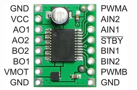
Pololu's Dual H-bridge breakout board
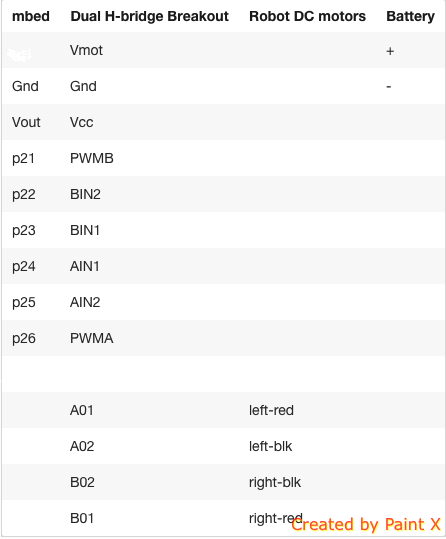
Wiring between mbed and dual H-bridge breakout board
Inertial Measurement Unit
A LSM9DS0 IMU breakout board is used to sense the acceleration and angular speed. A three-axis MEMS accelerometer is integrated with a three-axis MEMS gyroscope inside a single chip. By measuring and integrating the accelerations of the boat with proper adjustments, we can acquire real time linear speed of the boat. Readings from gyroscope tell us the angular speed of the boat on three axis. Dead reckoning from point A to point B can be achieved by incorporating linear speed and angular speed together.
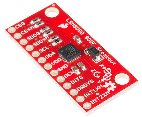
LSM9DS0 IMU breakout board
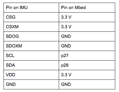
Wiring between mbed and IMU breakout board
XBee
Two XBee Pro 2B transceiver modules are used to establish a radio link between the laptop and the mbed microcontroller. XBee Pro S2B modules operate in ISM 2.4 GHz frequency band. On the mbed side, the module interfaces with the microcontroller through serial. On the side of Windows laptop, a USB-Serial adapter is used to establish the connection between Windows GUI and the RF module which will send the control command over the air.
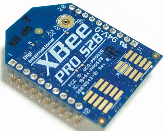
XBee Pro 2B breakout board
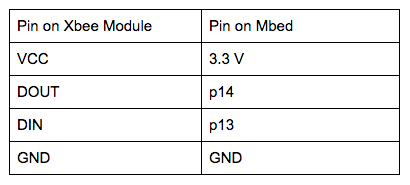
Wiring between mbed and XBee breakout board
System Breakdown
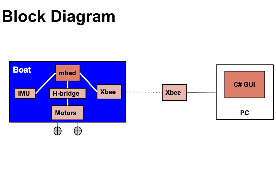
System diagram of self-adjusting robo-boat
C++ Implemented PID Control Loop
The IMU based PID control loop was implemented in C++ and runs on mbed microcontroller.
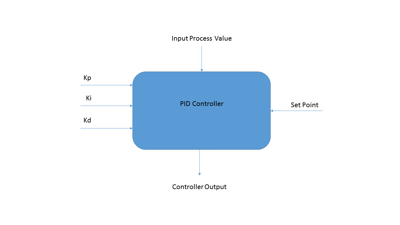
PID Loop Diagram
The PID loop is achieved by using a modified version of the PID controller from Aaron Berk. You can find his implementation here. The PID loop is expanded upon to enable tracking from the positive and negative side. In general, PID loops find the error between the set point and the current process variable. Next, the proportional term is multiplied to the error to get an output, additionally if there are integral (I) and derivative (D) terms, the derivative and integral of the terms from loop to loop is taken into account. More information on PID loops can be found in the Wikipedia PID loop entry. In this case, we find linear speed by integrating acceleration from the accelerometer and angular speed from the gyroscope of the LSM9DS0. The values are fed into two separate PID controllers to control the linear speed and angular speed independently. The set point and PID terms are set through the GUI, and the PID controller attempts to bring the process variable and set point as close as possible by controlling the motors. In ideal cases where the PID loop is tuned perfectly and the accelerometer is sensitive enough determine linear and angular speed reliably, the boat should be able to stay still and straight in a body of water with a current.
C# Windows GUI
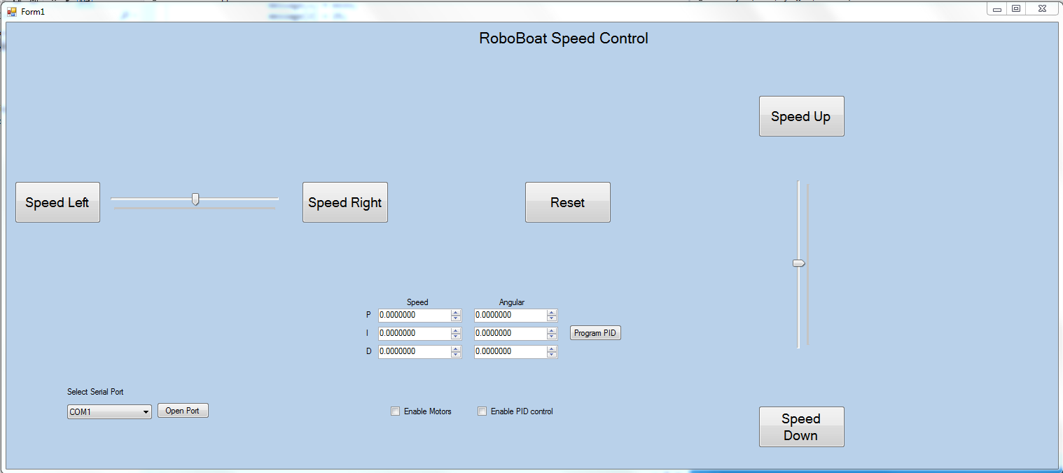 A C# Windows GUI was made for the user to control the boat remotely. The Reset button on the GUI sets the speed of both the propellers to 0. There is also a dropdown list that lets the user select the COM port that the XBee module is connected to on the computer. The appropriate COM port has to be selected before any control can be done.
The GUI consists of two slider bars that control the speed of the boat. One slider controls the forward speed of the boat and the other slider controls the angular speed of the boat. There is a "Enable Motors" checkbox that prompts the users to select if he/she wants to enable the motors. If the checkbox is selected, the motors respond according to the speed control from the GUI. If the checkbox is not selected, the propellers do not move.
The ‘Enable PID Loop’ prompts the user to select if he/she wants to implement the self-adjusting feature of the boat. If the checkbox is selected, the PID loop is enabled and the boat starts self adjusting according to the readings from the IMU. If it is not selected, the boat just follows the manual normal control from slider bars.
A text fields panel is included for advanced users to fine tune the Kp, Ki, and Kd parameters of the PID controllers for both the linear and angular speed of the boat. This function enables an Over The Air robo-boat programming method for users convenience.
The C# code for the GUI can be found on GitHub.
Manual Control Demonstration
Video demo for controlling the boat manually through Windows GUI and XBee Radio Link
PID Control Loop Demonstration
Video demo for controlling the boat through PID Loop without manual control (The P, I, D parameters are not fine tuned at this moment. Future work will be conducted to improve the loop performance)
Please log in to post comments.
