This is a work in progress. Trying to make a working arcade button to USB interface with the Nucleo F411RE.
This project was inspired by USB Joystick Device
The goal of this project is to build an simple interface that I will connect numerous Arcade buttons and joysticks to the Nucleo board, and the Nucleo will present itself as a USB Gamepad to Windows or Linux. The joysticks are Arcade joysticks that have four switches, up/down/left/right. It is not an analog joystick, just a set of switches. These will be connected to the Nucleo's pins configured as inputs.
The code will then continuously loop and test which buttons are closed, and transfer this data to the host via USBGamepad protocol.
Much thanks to Wim Huiskamp for his original project, documentation, and later reaching out to me to guide me to solving a last minute problem. Wim clued me into the fact that I needed a 1k5 pullup resistor between the 3v3 pin and the PA_12/D+ pin. Once I did this Windows detected the device as a Gamepad and registered it correctly! Yay!
Connecting USB cable to the board is as follows:
You will need a USB data cable (the one I used had a micro usb on one end and regular usb on the other). I cut off the micro USB end, and cut the insulation back about 30mm. This exposed four wires, Red, Black, White and Green. You will then either crimp some header connectors or solder directly to the Nucleo header pins as follows:
- Green USB D+ to PA_12
- White USB D- to PA_11
- Red USB 5V to E5V (with jumper JP5 set to E5V)
- Black USB GND to GND
As an extra debugging measure, you can connect both the ST/Link USB and the PA_12/11 USB to the Windows machine to run both at the same time, and you can see printf messages from within ST/Link.
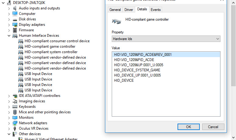
We can verify the HID Vendor and Product IDs by looking at the Device Manager, and look for the HID Game Controller:

I used pid.codes to register my own Vendor_ID and Product_ID
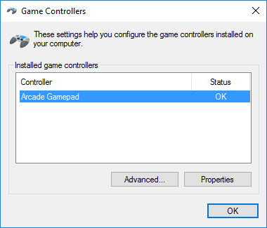
If you go to the USB Game Controller control panel widget, you will see the new entry for Arcade Gamepad:

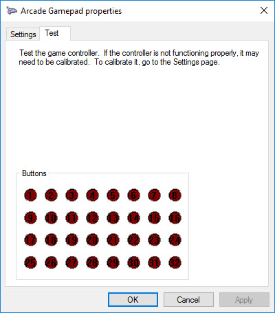
And here we can see all 32 buttons:

On the Nucleo board you may have difficulties depending on the revision. The board I am using is an STM32F411RE Revision C03, which has resistors and solder joints (bottom) to allow the use of the Crystal on the STLink board for USB purposes. After programming via STLink, remove the USB cable from the STLink, the jumper must be set to E5V to power the board from the PC's usb port. Plug the new cable into the PC.
When you're ready to install it in the arcade cabinet, or project, just remember to setup the jumper JP5 to E5V and you only need the single USB connection to the host.
Here are some useful links that I used to grasp all the little things involved in this project:
config.h@6:29a04fe27b5e, 2016-12-14 (annotated)
- Committer:
- thetazzbot
- Date:
- Wed Dec 14 15:30:55 2016 +0000
- Revision:
- 6:29a04fe27b5e
- Parent:
- 5:39b7e6653dae
Changed Report descriptor to implement a 2 player, 16 buttons each controller.
Who changed what in which revision?
| User | Revision | Line number | New contents of line |
|---|---|---|---|
| thetazzbot | 1:ad6066c16dbd | 1 | #define TARGET_STM32F4XX |
| thetazzbot | 1:ad6066c16dbd | 2 | #define NUM_OF_BUTTONS 32 |
| thetazzbot | 5:39b7e6653dae | 3 | #define SYSTEM_CLOCK_HZ 96000000 // 96MHz |
| thetazzbot | 1:ad6066c16dbd | 4 | |
| thetazzbot | 1:ad6066c16dbd | 5 | // Joystick button input pin assignments. |
| thetazzbot | 1:ad6066c16dbd | 6 | // |
| thetazzbot | 1:ad6066c16dbd | 7 | // You can wire up to 32 GPIO ports to buttons (equipped with |
| thetazzbot | 1:ad6066c16dbd | 8 | // momentary switches). Connect each switch between the desired |
| thetazzbot | 1:ad6066c16dbd | 9 | // GPIO port and ground (J9 pin 12 or 14). When the button is pressed, |
| thetazzbot | 1:ad6066c16dbd | 10 | // we'll tell the host PC that the corresponding joystick button is |
| thetazzbot | 1:ad6066c16dbd | 11 | // pressed. We debounce the keystrokes in software, so you can simply |
| thetazzbot | 1:ad6066c16dbd | 12 | // wire directly to pushbuttons with no additional external hardware. |
| thetazzbot | 1:ad6066c16dbd | 13 | // |
| thetazzbot | 1:ad6066c16dbd | 14 | // Note that we assign 24 buttons by default, even though the USB |
| thetazzbot | 1:ad6066c16dbd | 15 | // joystick interface can handle up to 32 buttons. VP itself only |
| thetazzbot | 1:ad6066c16dbd | 16 | // allows mapping of up to 24 buttons in the preferences dialog |
| thetazzbot | 1:ad6066c16dbd | 17 | // (although it can recognize 32 buttons internally). If you want |
| thetazzbot | 1:ad6066c16dbd | 18 | // more buttons, you can reassign pins that are assigned by default |
| thetazzbot | 1:ad6066c16dbd | 19 | // as LedWiz outputs. To reassign a pin, find the pin you wish to |
| thetazzbot | 1:ad6066c16dbd | 20 | // reassign in the LedWizPortMap array below, and change the pin name |
| thetazzbot | 1:ad6066c16dbd | 21 | // there to NC (for Not Connected). You can then change one of the |
| thetazzbot | 1:ad6066c16dbd | 22 | // "NC" entries below to the reallocated pin name. The limit is 32 |
| thetazzbot | 1:ad6066c16dbd | 23 | // buttons total. |
| thetazzbot | 1:ad6066c16dbd | 24 | // |
| thetazzbot | 1:ad6066c16dbd | 25 | // (If you're using TLC5940 chips to control outputs, many of the |
| thetazzbot | 1:ad6066c16dbd | 26 | // GPIO pins that are mapped to LedWiz outputs in the default |
| thetazzbot | 1:ad6066c16dbd | 27 | // mapping can be reassigned as keys, since the TLC5940 outputs |
| thetazzbot | 1:ad6066c16dbd | 28 | // take over for the GPIO pins. The exceptions are the pins that |
| thetazzbot | 1:ad6066c16dbd | 29 | // are reassigned to control the TLC5940 chips.) |
| thetazzbot | 1:ad6066c16dbd | 30 | // |
| thetazzbot | 1:ad6066c16dbd | 31 | // Note: PTD1 (pin J2-12) should NOT be assigned as a button input, |
| thetazzbot | 1:ad6066c16dbd | 32 | // as this pin is physically connected on the KL25Z to the on-board |
| thetazzbot | 1:ad6066c16dbd | 33 | // indicator LED's blue segment. |
| thetazzbot | 6:29a04fe27b5e | 34 | |
| thetazzbot | 1:ad6066c16dbd | 35 | PinName buttonMap[] = { |
| thetazzbot | 6:29a04fe27b5e | 36 | PA_3, // button 1 |
| thetazzbot | 6:29a04fe27b5e | 37 | PA_2, // button 2 |
| thetazzbot | 6:29a04fe27b5e | 38 | PA_10, // button 3 |
| thetazzbot | 6:29a04fe27b5e | 39 | PB_3, // button 4 |
| thetazzbot | 6:29a04fe27b5e | 40 | PB_5, // button 5 |
| thetazzbot | 6:29a04fe27b5e | 41 | PB_4, // button 6 |
| thetazzbot | 6:29a04fe27b5e | 42 | PB_10, // button 7 |
| thetazzbot | 6:29a04fe27b5e | 43 | PA_8, // button 8 |
| thetazzbot | 6:29a04fe27b5e | 44 | PA_9, // button 9 |
| thetazzbot | 6:29a04fe27b5e | 45 | PC_7, // button 10 |
| thetazzbot | 6:29a04fe27b5e | 46 | PB_6, // button 11 |
| thetazzbot | 6:29a04fe27b5e | 47 | PA_7, // button 12 |
| thetazzbot | 6:29a04fe27b5e | 48 | PA_6, // button 13 |
| thetazzbot | 6:29a04fe27b5e | 49 | PA_5, // button 14 |
| thetazzbot | 6:29a04fe27b5e | 50 | PB_9, // button 15 |
| thetazzbot | 6:29a04fe27b5e | 51 | PB_8, // button 16 |
| thetazzbot | 6:29a04fe27b5e | 52 | PC_9, // button 17 |
| thetazzbot | 6:29a04fe27b5e | 53 | PB_4, // button 18 |
| thetazzbot | 6:29a04fe27b5e | 54 | PB_13, // button 19 |
| thetazzbot | 6:29a04fe27b5e | 55 | PB_14, // button 20 |
| thetazzbot | 6:29a04fe27b5e | 56 | PB_15, // button 21 |
| thetazzbot | 6:29a04fe27b5e | 57 | PB_1, // button 22 |
| thetazzbot | 6:29a04fe27b5e | 58 | PB_2, // button 23 |
| thetazzbot | 6:29a04fe27b5e | 59 | PC_5, // button 24 |
| thetazzbot | 6:29a04fe27b5e | 60 | PC_6, // button 25 |
| thetazzbot | 6:29a04fe27b5e | 61 | PC_8, // button 26 |
| thetazzbot | 6:29a04fe27b5e | 62 | PH_1, // button 27 |
| thetazzbot | 6:29a04fe27b5e | 63 | PH_0, // button 28 |
| thetazzbot | 6:29a04fe27b5e | 64 | PC_15, // button 29 |
| thetazzbot | 6:29a04fe27b5e | 65 | PC_14, // button 30 |
| thetazzbot | 6:29a04fe27b5e | 66 | PC_13, // button 31 |
| thetazzbot | 6:29a04fe27b5e | 67 | PB_7 // button 32 |
| thetazzbot | 6:29a04fe27b5e | 68 | }; |
| thetazzbot | 1:ad6066c16dbd | 69 | |
| thetazzbot | 1:ad6066c16dbd | 70 | // STANDARD ID SETTINGS. These provide full, transparent LedWiz compatibility. |
| thetazzbot | 5:39b7e6653dae | 71 | const uint16_t USB_VENDOR_ID = 0x1209; |
| thetazzbot | 5:39b7e6653dae | 72 | const uint16_t USB_PRODUCT_ID = 0xACDE; |
| thetazzbot | 4:05f4ace9508a | 73 | const uint16_t USB_PRODUCT_VER = 0x0001; |