LPC1768 programming via 10pin JTAG/SW
Page last updated 06 Jun 2010, by  Jason Engelman.
7
replies
Jason Engelman.
7
replies
Jason Engelman.
7
replies
Introduction
This my CAN project graduating from the MBED platform on to a prototype board I recently made up. When I was putting this board together, I considered using ISP as the main programming method. But thought if this project ever got some momentum, it would be good to have JTAG ready for debugging. As I would think the next logical step would be to progress to the full Keil MDK with JTAG debugging unit. Anyway I don't have that, but I when I was first considering getting into embedded programming I also brought a LPCXpresso LPC1343 Dev Board. This device comes with the LPC1343 target and a weird JTAG/SW debugging board, anyway not to waste what I have. I have made use of the 10pin JTAG/SW port on my new proto board and the LPCXpresso device I have lying around collecting dust.
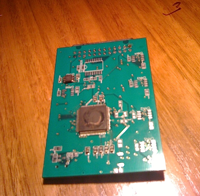
Bottom View Showing LPC1768
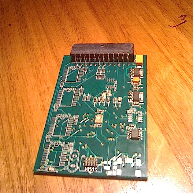
Top View Showing 10pin JTAG/SW port
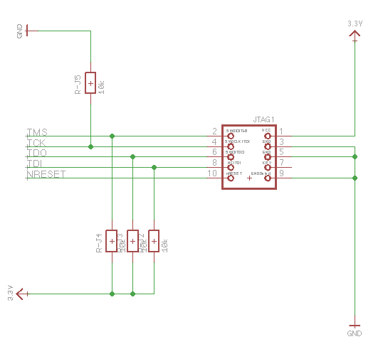
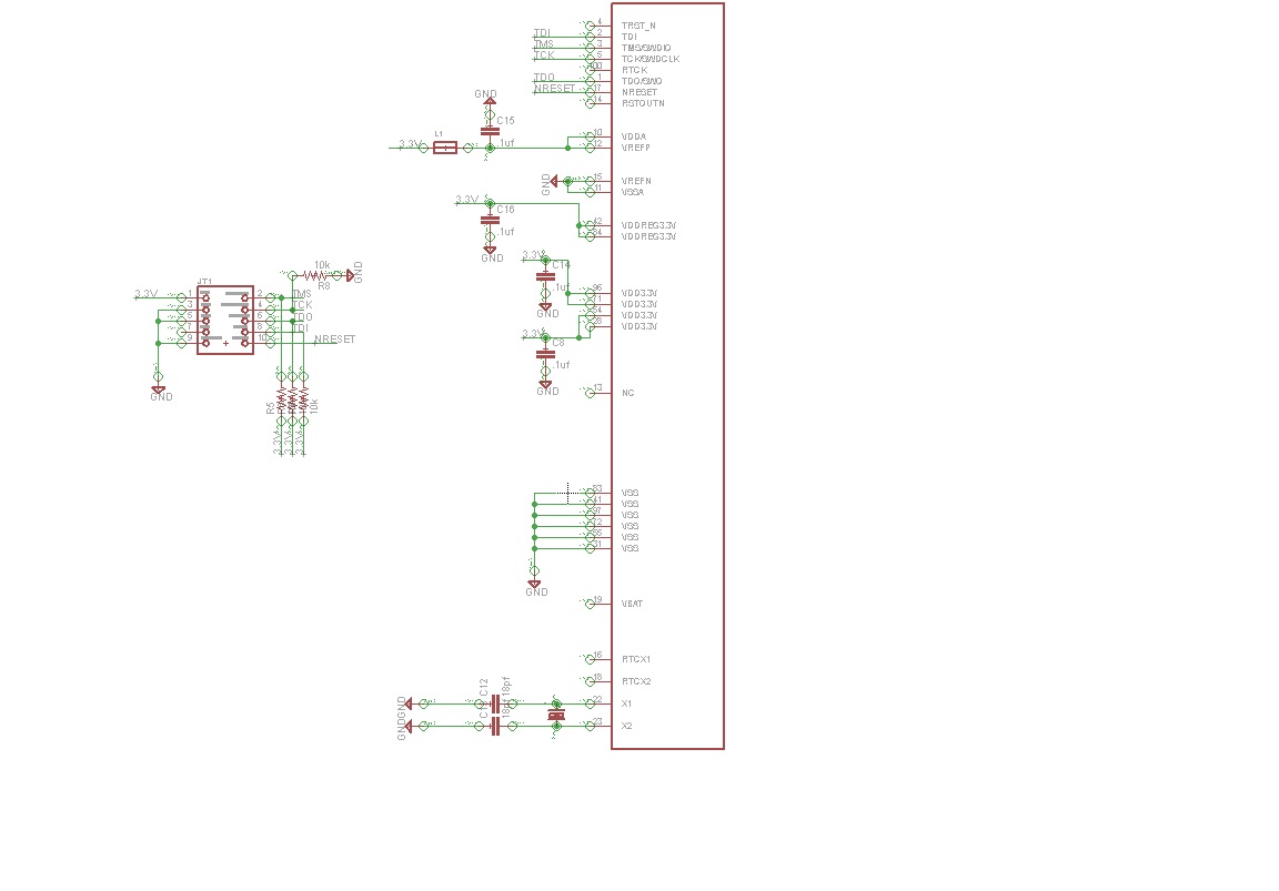
Schematic for 10pin JTAG/SW
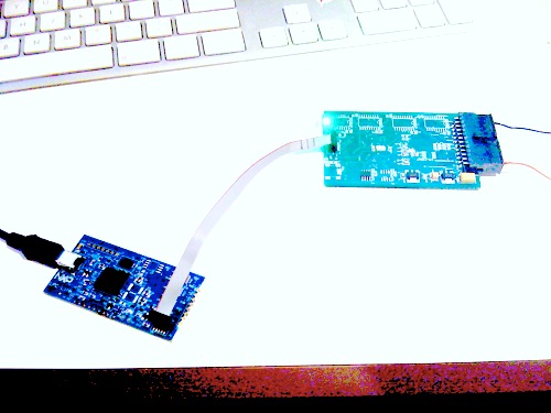
LPCLink connected to my prototype
Below are some commands which I found useful.
crt_emu_cm3_nxp.exe -wire=winusb -pLPC1768 -info-target
crt_emu_cm3_nxp.exe -wire=winusb -pLPC1768 -flash-load=FishNChips_LPC1768.bin -load-base=0x0000
C:\nxp\lpcxpresso_3.3\bin>crt_emu_cm3_nxp.exe -wire=winusb -pLPC1768 -flash-load=FishNChips_LPC1768.bin -load-base=0x0000
Ni: LPCXpresso Debug Driver v2.0 (Apr  8 2010 14:58:49)
Nc: Looked for chip XML file in C:/nxp/lpcxpresso_3.3/bin/LPC1768.xml

Nc: Looked for vendor directory XML file in C:/nxp/lpcxpresso_3.3/bin/nxp_directory.xml

Nc: Found generic directory XML file in C:/nxp/lpcxpresso_3.3/bin/crt_directory.xml

Wc: XML Warning from file C:/nxp/lpcxpresso_3.3/bin/nxp_lpcxxxx.xme: Unknown attribute package
Nc: NXP: LPC1768  Part ID: 26013F37
Cr:v Registered license, download limit of 128K
Nt: Loading binary file 'FishNChips_LPC1768.bin' at location 00000000
Nc: nSRST assert (if available)
Nc: Executing in user flash.

C:\nxp\lpcxpresso_3.3\bin>
7 comments
You need to log in to post a comment
LPC1768 programming via 10pin JTAG/SW
Page owner: Jason Engelman
Created 06 Jun 2010.
Last updated 06 Jun 2010
Thanks for the info.
This is quite useful since I too have an LPCXpresso board in the same fashion and can be used for this purpose.
Warm Regards,
Boseji
http://m8051.blogspot.com