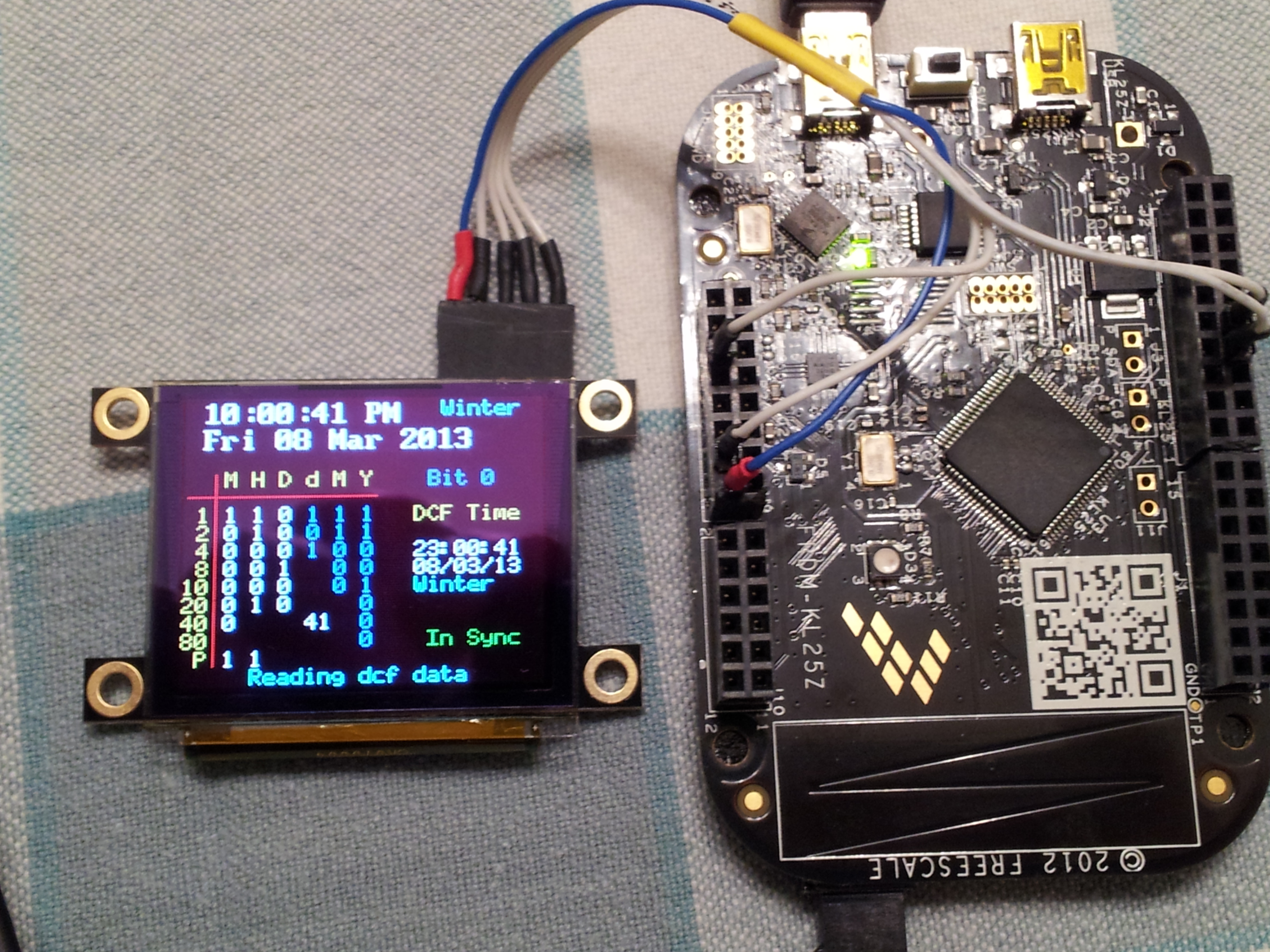
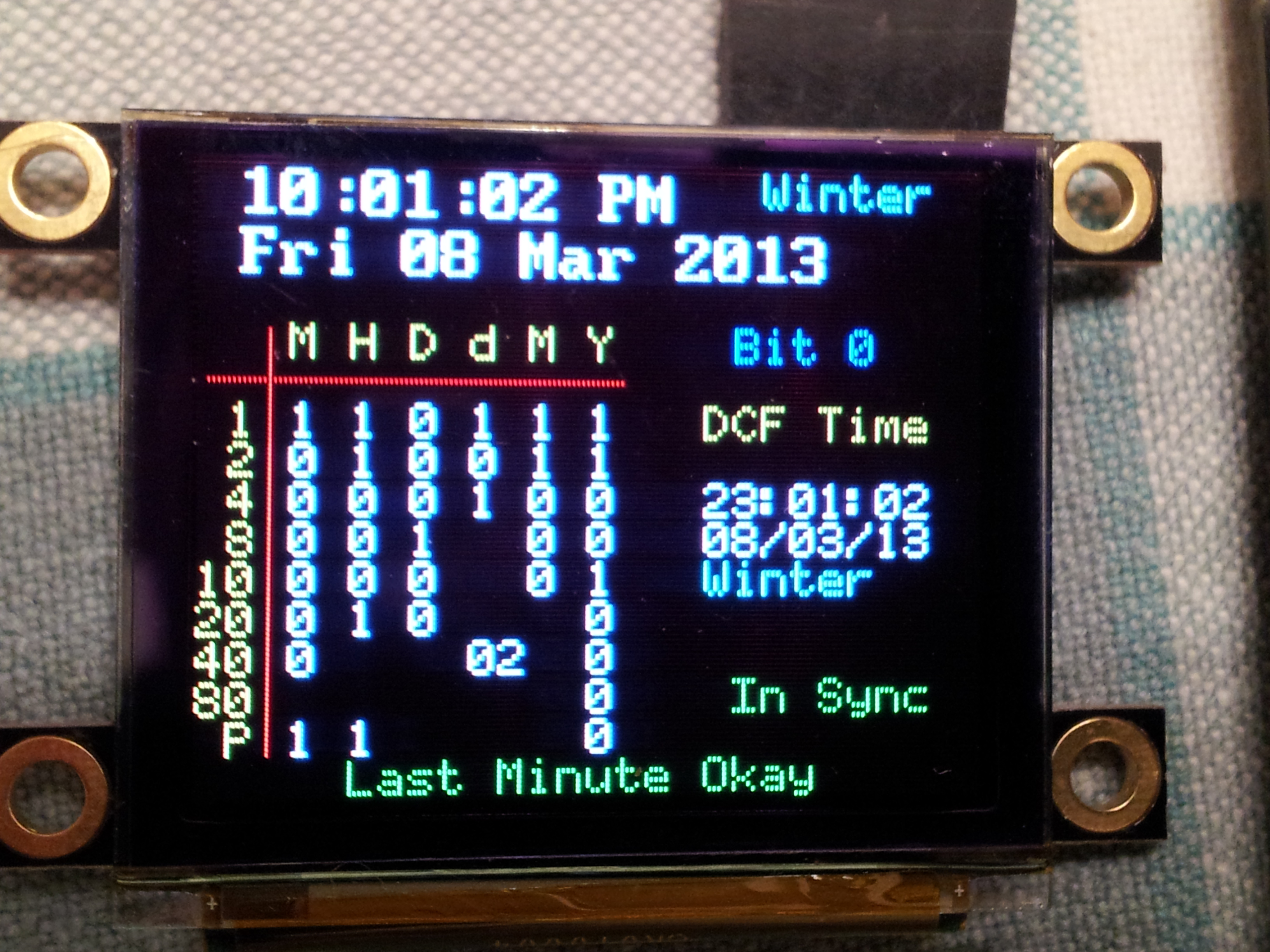
Freescale KL25Z DCF77 Atomic clock using 4D Systems uOLED160 OLED display. Displays a graphical display of DCF time signal bit build and sets the local clock time. The main signal timing is achieved by using a Ticker ISR that looks at the DCF signal input every 50mS this also produces the seconds on the local clock incase of signal errors or no signal. Many thanks to Lynton Towler for the idea of this part of the code and Wim who helped me convert it from an Arduino program. The Parity code was from Hans program that works. This dsiplay is considerably better that the nokia LCD.

Added RTC clock to top of display that is synchronised to the DCF clock on the middle right of display. Both clocks will continue to run with no signal and will synchronise to DCF when signal returns. The RTC clock is set to the DCF time less 3600 seconds that gives UK (GMT) time. Any multiples of 3600 seconds (1 hour) can be added or subtracted to give the correct RTC time depending on european location (see code line 349). The DCF clock will reset on power down however if the back up cell is fitted the RTC clock should continue to keep time and will display correct time when powered up again, I have not checked this yet. The DCF clock will reset and will synchronise within 2 minutes when power is supplied.

The DCF signal is sampled every 50mS each second that is called by the Interrupt Sub Routine (myISR). All code must be able to complete within 50mS otherwise it may cause the processor to 'hang' particularly durring Oled print functions that tend to be slow (even at 256k baud). So the trck here is to run parts of the code at different 50mS segments of the interrupt counter.
The program starts by looking for the 59th second pulse that is not transmitted, sample50 and sample150 will be zero at this point. When this arrives the interrupt counter is synchonised and the sample150 pulses are counted as '1's and '0's. The time and DCF bit map start on the 21st pulse with the last pulse counted at 58 seconds when partity is checked. If the parity is correct and the time variables are within limits as set in the partity_check subroutine, the DCF clock is set and then the RTC the process then repeats continuously alternating the bit map colour every DCF frame. If there is an error in the signal caused by a high level of noise or missing 'bits' the counters will restart looking for the 59th pulse.
This method of sampling has proved to be far more stable against noise in the DCF signal and will continue to run where as pulse width measuring method I have tried from other program examples requires an almost noise free signal.
I'm affraid the code is pretty poor and sure it could be much improved but it does work rather well.
I have made further checks on this board and have found that unlike the Mbed LPC1768 the coin cell is not for RTC back up. This battery is to run the CPU, RGB led and accelerometer and consumes around 15mA.
The other issue becomes apparent when the board is run from the coin cell and without power from the USB connector. In this case the SDA CPU is in 'sleep' mode that means the RTC clock signal is not generated and fed to the main CPU that results in the RTC freezing.
In conclusion the KL25Z would not be viable for general low power RTC clock functions that require the RTC to keep time when shut down.
Files at revision 1:4f254cca2bac
| Name | Size | Actions |
|---|---|---|
| [up] | ||
| OLED160G1.cpp | 5612 | Revisions Annotate |
| OLED160G1.h | 5696 | Revisions Annotate |