PCF2127 and PCF2129 are high accuracy real-time-clock (RTC) module. This library provides simple interface to accessing clock information.
Dependents: PCF2127_Demo PCF2127_Hello
PCF2127 and PCF2129
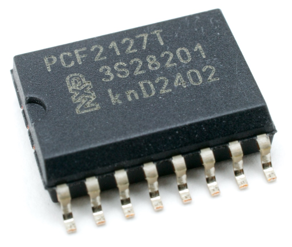
 PCF2127T is in SO16 package
The PCF2127 and the PCF2129 are a CMOS Real Time Clock (RTC) and calendar with an integrated Temperature Compensated Crystal (Xtal) Oscillator (TCXO) and a 32.768 kHz quartz crystal optimized for very high accuracy and very low power consumption.
Both of PCF2127 and PCF2129 have a selectable I2C-bus or SPI-bus, a backup battery switch-over circuit, a programmable watchdog function, a timestamp function, and many other features.
On addition to this, the PCF2127 has 512 bytes of general-purpose static RAM.
These 4 types of RTC modules are software compatible. So this library "PCF2127" can be used all of those.
This library only supports I2C to communicate with the PCF2127/PCF2129.
Type variations
Main feature difference
| type | +/-3ppm accuracy range | 512 bytes RAM | package |
|---|---|---|---|
| PCF2127T | -30℃ to +80℃ | yes | SO16 |
| PCF2127AT | -30℃ to +60℃ | yes | SO20 |
| PCF2129T | -30℃ to +80℃ | not available | SO16 |
| PCF2129AT | -15℃ to +60℃ | not available | SO20 |
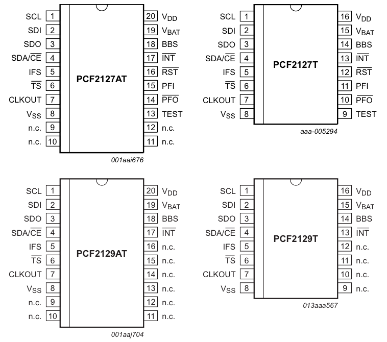
Pin assign


PCF2127T
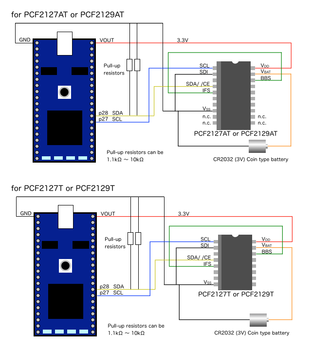
Connection between MCU and PCF2127/PCF2129
These examples show how the RTC module can be connected via I2C bus.

References
- Datasheet
- User manual
- Other information PCF2127
Diff: PCF2127.cpp
- Revision:
- 2:db76c68f998f
- Parent:
- 1:700e0285cfd8
- Child:
- 3:e2a6ac61fcbd
diff -r 700e0285cfd8 -r db76c68f998f PCF2127.cpp
--- a/PCF2127.cpp	Tue Dec 09 07:21:13 2014 +0000
+++ b/PCF2127.cpp	Wed Dec 10 01:43:30 2014 +0000
@@ -2,8 +2,8 @@
  *  PCF2127 library
  *
  *  @author     Akifumi (Tedd) OKANO, NXP Semiconductors
- *  @version    1.6
- *  @date       09-Dec-2014
+ *  @version    1.7
+ *  @date       10-Dec-2014
  *
  *  PCF2127 is a "real time clock (RTC)" module which is including a Xtal and TCXO
  *  http://www.nxp.com/products/interface_and_connectivity/real_time_clocks/rtcs_with_temp_compensation/series/PCF2127.html
@@ -42,12 +42,12 @@
 {
     char    data[ 4 ];
     int     err;
-
+
     data[ 0 ]   = Control_1; //  access start register address
     data[ 1 ]   = vControl_1;
     data[ 2 ]   = vControl_2;
     data[ 3 ]   = vControl_3;
-
+
     err     = i2c.write( device_address, data, sizeof( data ) );
     err    |= set_register( CLKOUT_ctl, vCLKOUT_ctl );

@@ -74,7 +74,7 @@
     buf[ 7 ]    = i2bcd( dtp->tm_year - 100 );

     err = i2c.write( device_address, buf, 8 );
-
+
     return ( err ? I2C_ACCESS_FAIL : NO_ERROR );
 }

@@ -138,7 +138,7 @@
     char    v;

     v   = i2bcd( s );
-
+
     return ( set_register( addr, v ) );
 }

@@ -147,6 +147,46 @@
     return ( set_register( Control_2, 0x00 ) );
 }

+int PCF2127::RAM_write( int address, char *p, int size )
+{
+    char    b[ size + 1 ];
+
+    b[ 0 ]  = RAM_wrt_cmd;
+
+    for ( int i = 1; i <= size; i++ )
+        b[ i ]  = *p++;
+
+    if ( set_RAM_address( address ) )
+        return ( I2C_ACCESS_FAIL );
+
+    return ( i2c.write( device_address, b, sizeof( b ) ) ? I2C_ACCESS_FAIL : NO_ERROR );
+}
+
+int PCF2127::RAM_read( int address, char *p, int size )
+{
+    char    b   = RAM_rd_cmd;
+
+    if ( set_RAM_address( address ) )
+        return ( I2C_ACCESS_FAIL );
+
+    if ( i2c.write( device_address, &b, 1 ) )
+        return ( I2C_ACCESS_FAIL );
+
+    return ( i2c.read( device_address, p, size ) ? I2C_ACCESS_FAIL : NO_ERROR );
+}
+
+
+int PCF2127::set_RAM_address( char address )
+{
+    char    b[ 3 ];
+
+    b[ 0 ]  = RAM_addr_MSB;
+    b[ 1 ]  = (address >> 8) & 0x1;
+    b[ 2 ]  = address & 0xFF;
+
+    return ( i2c.write( device_address, b, sizeof( b ) ) );
+}
+
 int PCF2127::set_register( char addr, char data )
 {
     char    b[ 2 ];
@@ -154,7 +194,7 @@
     b[ 0 ]    = addr;
     b[ 1 ]    = data;

-    return ( i2c.write( device_address, b, 2 ) );
+    return ( i2c.write( device_address, b, sizeof( b ) ) );
 }

 int PCF2127::read_register( char addr )
 PCF2127 and PCF2129 High-accuracy RTC module