The PCAL9555, PCAL9554 series is a low-voltage 16-bit/8-bit General Purpose Input/Output (GPIO) expander with interrupt. This conponent library is compatible to basic operation os GPIO expanders: PCAL9555, PCA9555, PCA9535, PCA9539, PCAL9554, PCA9554 and PCA9538. On addition to this, this library is including mbed-SDK-style APIs. APIs that similar to DigitaiInOut, DigitalOut, DigitalIn, BusInOUt, BusOut and BusIn are available.
Dependents: PCAL9555_Hello OM13082-JoyStick OM13082_LED OM13082-test ... more
What is this?
This conponent library is compatible to basic operation os GPIO expanders: PCAL9555, PCA9555, PCA9535, PCA9539, PCAL9554, PCA9554 and PCA9538 .
On addition to this, this library is including mbed-SDK-style APIs. APIs that similar to DigitaiInOut, DigitalOut, DigitalIn, BusInOut, BusOut and BusIn are available.
How to use?
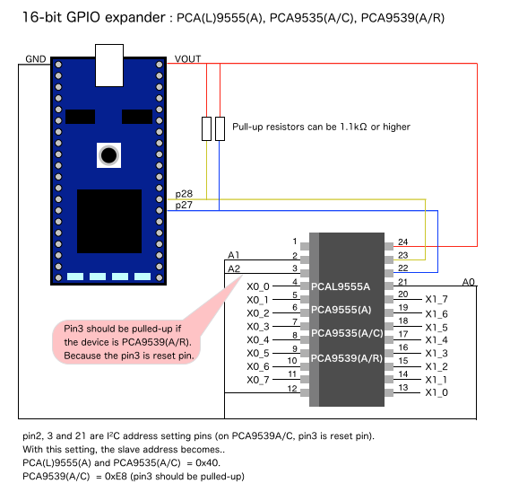
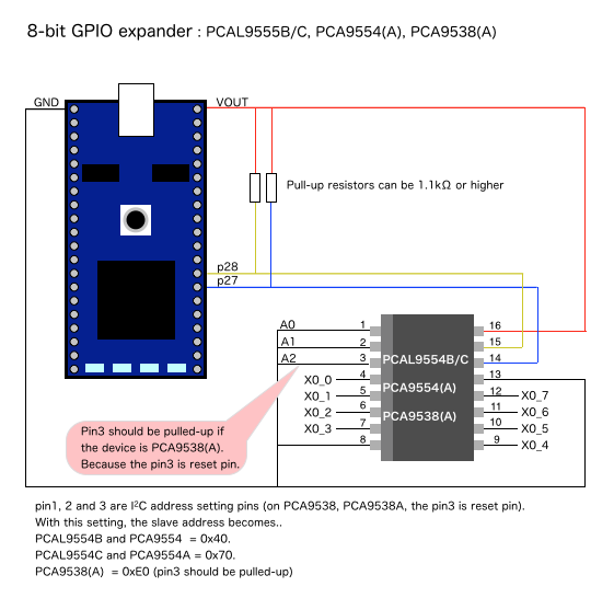
Wiring

Wiring between mbed and 16-bit GPIO expander

Wiring between mbed and 8-bit GPIO expander
Very basic register level I/O bit operation
PCAL9555 and PCAL9554 are class libraries for those compatible GPIO expander chips.
Those class libraries provides interface for bit operation of its I/O port.
For 16-bit GPIO expanders, the input/output access and its direction setting can be done by 16-bit data. For 8-bit GPIO expanders, those can be done by 8-bit data.
  #include    "mbed.h"
  #include    "PCAL9555.h"

  PCAL9555    gpio( p28, p27, 0xE8 );     //  using PCA9539

  int main() {
      gpio.configure( 0xFFFF );           //  Set all pins: input
      printf( "  0x%04X\r\n", (int)gpio );//  Print pins state

      gpio.configure( 0x0000 );           //  Set all pins: output
      int count   = 0;
      while(1) {
          gpio.write( count++ );
      }
  }
High level APIs
To use the GPIO expanders more simple, this library is including mbed-SDK-style APIs.
APIs that similar to DigitaiInOut, DigitalOut, DigitalIn, BusInOut, BusOut and BusIn are available.
GpioDigitalOut, GpioDigitaiInOut, GpioDigitalIn
Next code shows sample of DigitalOut equivalent API GpioDigitalOut usage.
A pin on the PCAL9555 is defined as pin and its state is changed by assignment.
(For single pin operation, GpioDigitaiInOut and GpioDigitalIn are available also.)
  #include "mbed.h"
  #include "PCAL9555.h"

  PCAL9555        gpio_exp( p28, p27, 0xE8 );    //  SDA, SCL, Slave_address(option)
  GpioDigitalOut  pin( gpio_exp, X0_0 );

  int main() {
      while( 1 ) {
          pin = 1;
          wait( 0.2 );
          pin = 0;
          wait( 0.2 );
      }
  }
GpioBusOut, GpioBusInOut, GpioBusIn
BusOut equivalent API GpioBusOut is available too.
In next code, pins are grouped as mypins to manage the output as bus output.
(Same as GpioDigitalInOut and GpioDigitalIn APIs, GpioBusInOut and GpioBusIn are available also.)
  #include "mbed.h"
  #include "PCAL9555.h"

  PCAL9555    gpio_exp( p28, p27, 0xE8 );    //  SDA, SCL, Slave_address(option)
  GpioBusOut  mypins( gpio_exp, X0_0, X0_1, X0_2, X0_3 );

  int main() {
      while( 1 ) {
          for( int i = 0; i < 16; i++ ) {
              mypins  = i;
              wait( 0.25 );
          }
      }
  }
The high level APIs can be used in combination
Those high level APIs can be used in combination.
Each pins can be managed by instances.
  #include    "mbed.h"
  #include    "PCAL9555.h"

  PCAL9555        gpio( p28, p27, 0xE8 );     //  using PCA9539

  //  The GPIO pins are grouped in some groups and operated as bus I/O
  GpioBusIn       bus_in( gpio, X0_0, X0_1, X0_2, X0_3 );
  GpioBusOut      bus_out( gpio, X0_4, X0_5, X0_6 );
  GpioBusInOut    bus_io( gpio, X1_7, X1_6, X1_5, X1_4, X1_3, X1_2, X1_1, X1_0 );
  GpioDigitalOut  myled( gpio, X0_7 );

  int main() {
      bus_io.input();
      printf( "I/O = 0x%02X\r\n", (int)bus_io );
      printf( "In  = 0x%01X\r\n", (int)bus_in );

      bus_io.output();

      int count   = 0;
      while(1) {
          bus_out = count;
          bus_io  = count;
          myled   = count & 0x1;
          count++;
          wait( 0.1 );
      }
  }
PCAL9555/PCAL9555.h
- Committer:
- nxp_ip
- Date:
- 2015-03-19
- Revision:
- 1:fd7cfa821b6a
- Parent:
- 0:6c9a51a50eea
File content as of revision 1:fd7cfa821b6a:
/** PCA(L)9555 16-bit I2C-bus GPIO expander
 *
 *  An operation sample of PCA(L)9555, PCA9535 and PCA9539.
 *  mbed accesses the PCAL9555 registers through I2C.
 *
 *  @class   PCAL9555
 *  @author  Akifumi (Tedd) OKANO, NXP Semiconductors
 *  @version 0.6
 *  @date    19-Mar-2015
 *
 *  Released under the Apache 2 license
 *
 *  About PCAL9555:
 *    http://www.nxp.com/products/interface_and_connectivity/i2c/i2c_general_purpose_i_o/series/PCAL9555A.html
 */

#ifndef     MBED_PCAL9555
#define     MBED_PCAL9555

#include    "mbed.h"
#include    "PCAL955x.h"
#include    "CompGpioExpAPI.h"

/** PCAL9555 class
 *
 *  This is a driver code for the Low-voltage 16-bit I2C-bus GPIO with Agile I/O.
 *  This class provides interface for PCAL9555 operation.
 *  Detail information is available on next URL.
 *    http://www.nxp.com/products/interface_and_connectivity/i2c/i2c_general_purpose_i_o/series/PCAL9555A.html
 *
 *  PCAL9555 library's basic IO operation is compatible to PCA9555, PCA9535 and PCA9539.
 *  This library can be used for those GPIO expander chips also.
 *  Next sample code shows operation based on low-level-API (operated by just device instane)
 *
 *  Example:
 *  @code
 *  //  GPIO-expander operation sample using a device instance
 *
 *  #include    "mbed.h"
 *  #include    "PCAL9555.h"
 *
 *  PCAL9555    gpio( p28, p27, 0xE8 );     //  using PCA9539
 *
 *  int main() {
 *      gpio.configure( 0xFFFF );           //  Set all pins: input
 *      printf( "  0x%04X\r\n", (int)gpio );//  Print pins state
 *
 *      gpio.configure( 0x0000 );           //  Set all pins: output
 *      int count   = 0;
 *      while(1) {
 *          gpio.write( count++ );
 *      }
 *  }
 *  @endcode
 *
 *  GpioDigitalInOut, GpioDigitalOut, GpioDigitalIn,
 *  GpioBusInOut, GpioBusOut and GpioBusIn API class are available also.
 *  For those high-level-API details, please find those class library page.
 *  The GpioDigital* and GpioBus* APIs can be used like next sample code.
 *
 *  @code
 *  //  GPIO-expander operation sample using high-level-API
 *
 *  #include    "mbed.h"
 *  #include    "PCAL9555.h"
 *
 *  PCAL9555        gpio( p28, p27, 0xE8 );     //  using PCA9539
 *
 *  //  The GPIO pins are grouped in some groups and operated as bus I/O
 *  GpioBusIn       bus_in( gpio, X0_0, X0_1, X0_2, X0_3 );
 *  GpioBusOut      bus_out( gpio, X0_4, X0_5, X0_6 );
 *  GpioBusInOut    bus_io( gpio, X1_7, X1_6, X1_5, X1_4, X1_3, X1_2, X1_1, X1_0 );
 *  GpioDigitalOut  myled( gpio, X0_7 );
 *
 *  int main() {
 *      bus_io.input();
 *      printf( "I/O = 0x%02X\r\n", (int)bus_io );
 *      printf( "In  = 0x%01X\r\n", (int)bus_in );
 *
 *      bus_io.output();
 *
 *      int count   = 0;
 *      while(1) {
 *          bus_out = count;
 *          bus_io  = count;
 *          myled   = count & 0x1;
 *          count++;
 *          wait( 0.1 );
 *      }
 *  }
 *  @endcode
 */

class PCAL9555 : public PCAL955x
{
public:
    /** Name of the PCAL9555 registers */
    enum command_reg {
        InputPort0              = 0x00, /**< InputPort0 register                */
        InputPort1,                     /**< InputPort1 register                */
        OutoutPort0,                    /**< OutoutPort0 register               */
        OutoutPort1,                    /**< OutoutPort1 register               */
        PolarityInversionPort0,         /**< PolarityInversionPort0 register    */
        PolarityInversionPort1,         /**< PolarityInversionPort1 register    */
        ConfigurationPort0,             /**< ConfigurationPort0 register        */
        ConfigurationPort1,             /**< ConfigurationPort1 register        */
        OutputDriveStrength0_0  = 0x40, /**< OutputDriveStrength0_0 register    */
        OutputDriveStrength0_1,         /**< OutputDriveStrength0_1 register    */
        OutputDriveStrength1_0,         /**< OutputDriveStrength1_0 register    */
        OutputDriveStrength1_1,         /**< OutputDriveStrength1_1 register    */
        InputLatch0,                    /**< InputLatch0 register               */
        InputLatch1,                    /**< InputLatch1 register               */
        PullUpPullDowmEnable0,          /**< PullUpPullDowmEnable0 register     */
        PullUpPullDowmEnable1,          /**< PullUpPullDowmEnable1 register     */
        PullUpPullDowmSelection0,       /**< PullUpPullDowmSelection0 register  */
        PullUpPullDowmSelection1,       /**< PullUpPullDowmSelection1 register  */
        InterruptMask0,                 /**< InterruptMask0 register            */
        InterruptMask1,                 /**< InterruptMask1 register            */
        InterruptStatus0,               /**< InterruptStatus0 register          */
        InterruptStatus1,               /**< InterruptStatus1 register          */
        OutputPortConfiguration = 0x4F, /**< OutputPortConfiguration register   */
    };

#if DOXYGEN_ONLY
    /** GPIO-Expander pin names
     *    for when the high-level APIs
     *    (GpioDigitalOut, GpioDigitalInOut, GpioDigitalIn,
     *    GpioBusOut, GpioBusInOut are GpioBusIn) are used
     */
    typedef enum {
        X0_0,           /**< P0_0 pin */
        X0_1,           /**< P0_1 pin */
        X0_2,           /**< P0_2 pin */
        X0_3,           /**< P0_3 pin */
        X0_4,           /**< P0_4 pin */
        X0_5,           /**< P0_5 pin */
        X0_6,           /**< P0_6 pin */
        X0_7,           /**< P0_7 pin */
        X1_0,           /**< P1_0 pin */
        X1_1,           /**< P1_1 pin */
        X1_2,           /**< P1_2 pin */
        X1_3,           /**< P1_3 pin */
        X1_4,           /**< P1_4 pin */
        X1_5,           /**< P1_5 pin */
        X1_6,           /**< P1_6 pin */
        X1_7,           /**< P1_7 pin */
        X0  = X0_0,     /**< P0_0 pin */
        X1  = X0_1,     /**< P0_1 pin */
        X2  = X0_2,     /**< P0_2 pin */
        X3  = X0_3,     /**< P0_3 pin */
        X4  = X0_4,     /**< P0_4 pin */
        X5  = X0_5,     /**< P0_5 pin */
        X6  = X0_6,     /**< P0_6 pin */
        X7  = X0_7,     /**< P0_7 pin */
        X8  = X1_0,     /**< P1_0 pin */
        X9  = X1_1,     /**< P1_1 pin */
        X10 = X1_2,     /**< P1_2 pin */
        X11 = X1_3,     /**< P1_3 pin */
        X12 = X1_4,     /**< P1_4 pin */
        X13 = X1_5,     /**< P1_5 pin */
        X14 = X1_6,     /**< P1_6 pin */
        X15 = X1_7,     /**< P1_7 pin */

        X_NC = ~0x0L    /**< for when the pin is left no-connection */
    } GpioPinName;
#endif

    /** Create a PCAL9555 instance connected to specified I2C pins with specified address
     *
     * @param i2c_sda       I2C-bus SDA pin
     * @param i2c_sda       I2C-bus SCL pin
     * @param i2c_address   I2C-bus address (default: 0x40)
     */
    PCAL9555( PinName i2c_sda, PinName i2c_scl, char i2c_address = PCAL955x::DEFAULT_I2C_ADDR );

    /** Create a PCAL9555 instance connected to specified I2C pins with specified address
     *
     * @param i2c_obj       I2C object (instance)
     * @param i2c_address   I2C-bus address (default: 0x40)
     */
    PCAL9555( I2C &i2c_obj, char i2c_address = PCAL955x::DEFAULT_I2C_ADDR );

    /** Destractor
     */
    virtual         ~PCAL9555();

    /** Returns the number of I/O pins
     *
     *  @returns
     *    The number of I/O pins
     */
    virtual int     number_of_pins( void );

#if DOXYGEN_ONLY

    /** Set output port bits
     *
     *  @param bit_pattern  16-bit output pattern for port1 and port0.
     *
     *  @note
     *    The data for pins, given as integer.
     *    The 16-bit MSB goes to P1_7 pin and LSB goes to P0_0 pin.
     *    Data will not come out from the pin if it is configured as input.
     *
     *  @see configure()
     */
    void            write( int bit_pattern );

    /** Read pin states
     *
     *  @return
     *    16-bit pattern from port1 and port0.
     *
     *  @note
     *    The data from pins, given as integer.
     *    The 16-bit port data comes from IO pins, P1_7 as MSB, P0_0 as LSB.
     *    Data cannot be read if the port is configured as output.
     *
     *  @see configure()
     */
    int             read( void );

    /** Polarity setting
     *
     *  @param bit_pattern  16-bit polarity setting pattern for port1 and port0.
     *    If the bit is set to '1', the state will be inverted.
     *    (Default state is all '0')
     *
     *  @see configure()
     */
    void            polarity( int bit_pattern );

    /** Set IO congiguration
     *
     *  @param bit_pattern  16-bit IO direction setting pattern for port1 and port0.
     *
     *  @note
     *    The data for pins, given as integer.
     *    The 16-bit MSB goes to P1_7 pin and LSB goes to P0_0 pin.
     *    If the bit is set to '1', the pin will be input.
     *
     *  @see write()
     *  @see read()
     */
    void            configure( int bit_pattern );

    /** Set interrupt mask
     *
     *  @param bit_pattern  16-bit interrupt mask
     *
     *  @see interrupt_status()
     */
    void            interrupt_mask( int bit_pattern );

    /** Read interrupt status
     *
     *  @return
     *    16-bit data from interrupt status registers
     *
     *  @see interrupt_status()
     */
    int             interrupt_status( void );

    /** A shorthand for read()
     */
    operator int( void );

#endif

    /** Write 16-bit data into registers
     *
     *  @param reg_index    Direst access to registers.
     *    The registers can be referenced by regiser index
     *  @param data  16-bit data. Data will be written into two 8-bit registers
     */
    virtual void    reg_index_write( char register_index, int data );

    /** Read 16-bit data from registers
     *
     *  @param reg_index    Direst access to registers.
     *    The registers can be referenced by regiser index
     *
     *  @return
     *    16-bit data from two registers.
     *    The register which has lower address will be upper 8-bit data.
     */
    virtual int     reg_index_read( char register_index );

    /** A shorthand for write()
     */
    PCAL9555&       operator= ( int bit_pattern );
    PCAL9555&       operator= ( PCAL9555& rhs );

private:
    /** Register index name */
    enum RegisterIndex {
        InputPort               = InputPort0,
        OutoutPort              = OutoutPort0,
        PolarityInversionPort   = PolarityInversionPort0,
        ConfigurationPort       = ConfigurationPort0,
        OutputDriveStrength0    = OutputDriveStrength0_0,
        OutputDriveStrength1    = OutputDriveStrength1_0,
        InputLatch              = InputLatch0,
        PullUpPullDowmEnable    = PullUpPullDowmEnable0,
        PullUpPullDowmSelection = PullUpPullDowmSelection0,
        InterruptMask           = InterruptMask0,
        InterruptStatus         = InterruptStatus0
    };

    static const char   regmap[];
    const int           n_of_pins;
}
;

#endif  //  MBED_PCAL9555
 PCAL9555, PCAL9554: 16 & 8-bit GPIO expander with "DigitalInOut" and "BusInOut" compatible APIs